
PMDD Stator Insulation & dV/dt Filter Sizing: Cable Reflection, PDIV Limits, and Output Filter Selection
Compare PMDD stator insulation and dV/dt filter sizing: cable reflection, PDIV evidence, and drive limits. Prepare an RFQ for a supplier compatibility review.
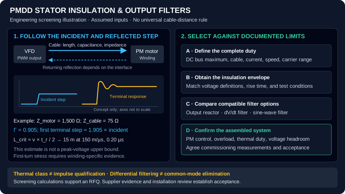
Quick answer: PMDD stator insulation and dV/dt filter sizing require a coordinated motor, drive, and cable assessment. Long cables and fast inverter edges can raise motor-terminal voltage through reflection. Start with the drive's maximum DC bus voltage, pulse rise time, routed cable length, and the motor supplier's allowable impulse envelope. Compare an output reactor, a dV/dt filter, and a sine-wave filter against those limits. Neither a Class H label nor a universal 15 m or 100 m cable rule establishes compatibility.
Published and reviewed: November 6, 2026 · Global · Publisher: PMDD Motor. This guide supports engineering screening and RFQ preparation for low-voltage, three-phase, inverter-fed permanent magnet direct drive motors. It covers insulation stress, partial discharge inception voltage (PDIV), and output filter selection. Numerical examples are illustrative calculations, not measured motor performance, product approvals, or service-life predictions. Medium-voltage machines and hazardous-area installations require their own documented qualification and installation review.
For an active project, send your motor current, drive model, supply voltage, and routed cable length for supplier compatibility review.
The header schematic is a conceptual screening aid. Open the full-size cable reflection and output filter diagram to inspect the assumptions and decision sequence; it is not a measured waveform or manufacturing record.
Match the terminal waveform to the documented insulation envelope
- L_crit ≈ v × t_r / 2 [first reflection screening estimate]
- Gamma = (Z_m - Z_c) / (Z_m + Z_c) [simplified reflection coefficient]
- V_terminal ≈ V_incident × (1 + Gamma) [first arriving step]
- f_e = pole_pairs × rpm / 60 [electrical fundamental frequency]
- f_0 = 1 / (2 × pi × sqrt(L × C)) [ideal equivalent LC resonance]
- Thermal class and impulse-voltage capability describe different properties; request both.
- Cable length is a screening input. Rise time, bus voltage, cable capacitance, and motor insulation determine the actual filter requirement.
- A differential sine-wave filter does not automatically remove phase-to-ground common-mode stress or bearing currents.
- Filter current, overload duration, operating frequency, cooling, and PM motor control compatibility must be checked together.
- Drive model, firmware, control mode, DC bus maximum, and switching-frequency range.
- Motor current, overload duty, pole count, maximum speed, and impulse qualification evidence.
- Actual cable route, cable construction, capacitance, parallel runs, and grounding arrangement.
- Required terminal voltage envelope, filter losses, voltage drop, and commissioning acceptance records.
1. Why Remote Direct-Drive Motors Need an Electrical Interface Review
In cooling towers, conveyors, mixers, and extruders, the variable frequency drive (VFD) may sit in a motor control center while the PMDD motor is mounted at the machine. The cable between them is part of the electrical system. Its distributed inductance and capacitance affect the steep edges of pulse-width-modulated (PWM) voltage even when the fundamental motor frequency is low.
A low-speed motor is therefore not automatically a low-stress insulation application. Mechanical speed sets the required electrical fundamental through pole count, while inverter edge speed determines high-frequency excitation. Reducing shaft speed does not necessarily slow those edges. A procurement specification that lists only motor kilowatts, thermal class, and cable distance leaves important interface conditions undefined.
Repeated impulses can stress turn-to-turn, phase-to-phase, and phase-to-ground insulation differently. Localized winding damage can be consistent with electrical stress, but it does not prove a reflected-wave or partial-discharge failure. Moisture, contamination, mechanical damage, winding defects, cooling problems, and incorrect connections also need investigation. This guide does not report a field-failure population or claim a particular failure timeline.
The practical goal is to assign responsibility before ordering: the motor supplier declares the qualified insulation envelope, the drive and filter suppliers declare compatible operating conditions, and the integrator verifies the assembled installation. IEC TS 60034-25:2022 provides the application framework for converter-fed AC machines and their system interactions. Its catalogue description does not establish a universal filter requirement for every PMDD installation.
2. Cable Reflection: Useful Calculations and Their Limits
Pulse travel time and critical cable length
For a simplified cable model, compare one-way propagation time with inverter voltage rise time:
t_d = cable_length / propagation_velocity
L_crit ≈ propagation_velocity × rise_time / 2
Use the cable manufacturer's propagation data where available. As an illustrative assumption, take a propagation velocity of 150 m/µs. With a drive rise time of 0.20 µs, the estimated critical length is 15 m; at 0.08 µs it is 6 m. These numbers explain why changing the drive power stage can change the electrical stress without changing the cable.
This is an approximate screening threshold for a substantial first reflection, not a guaranteed onset of exactly twice the bus voltage. When the round-trip cable travel time is comparable to or longer than the rising edge, the cable cannot be treated as a lumped connection for that edge. Source impedance, losses, motor impedance, and pulse spacing affect the resulting waveform.
Reflection coefficient and terminal peak
For an idealized single arriving voltage step:
Gamma = (Z_motor - Z_cable) / (Z_motor + Z_cable)
V_terminal_step = V_incident_step × (1 + Gamma)
With assumed surge impedances of 1,500 Ω for the motor and 75 Ω for the cable, the reflection coefficient is 0.905 and the terminal step is approximately 1.905 times the incident step. Those impedances are example inputs, not PMDD motor specifications. Real winding impedance varies with frequency and winding construction.
If the incident step is approximated by the DC bus voltage, the familiar near-doubling estimate follows. Multiple reflections and closely spaced pulses can produce different peaks, including peaks above this simple estimate. Measure or model the actual circuit when determining an acceptance limit; a first-reflection calculation is not an upper bound.
Supply-voltage screening table
The following arithmetic assumes a DC bus of approximately the square root of two times nominal line-to-line RMS supply voltage and a first-reflection multiplier of 1.905. Values are rounded to the nearest volt. An active front end, regeneration, supply tolerance, and braking control can change the actual bus maximum. No row establishes safe operation or a required filter topology.
| Supply voltage, line-to-line RMS | Assumed DC bus | Illustrative first-reflection step | Evidence needed before acceptance |
|---|---|---|---|
| 380 V | 537 V | 1,024 V | Actual bus maximum and motor impulse envelope |
| 400 V | 566 V | 1,078 V | Rise time and allowable repetitive terminal stress |
| 460 V | 651 V | 1,239 V | Cable parameters and supplier insulation evidence |
| 480 V | 679 V | 1,293 V | Regenerative bus conditions and terminal waveform |
| 575 V | 813 V | 1,549 V | Voltage-class-specific drive and filter approval |
| 690 V | 976 V | 1,859 V | Qualified insulation and filter limits for this voltage |
Keep the voltage definitions explicit. A line-to-line peak, a phase-to-ground peak, a peak-to-peak value, and a turn-to-turn test voltage are different quantities. Comparing them directly can create a fictitious insulation margin.
3. PDIV, First-Turn Stress, and Insulation Qualification
Fast impulses do not distribute across a winding in the same way as the fundamental voltage. Distributed winding capacitance and inductance can concentrate transient stress near the line end. The proportion across any individual turn depends on the winding arrangement and applied waveform. A fixed claim that 70% to 85% always appears across the first turn is not an adequate design basis.
Partial discharge is a localized breakdown in part of an insulation system. Repeated activity can erode susceptible insulation. PDIV is the applied voltage at which discharge is detected under specified test conditions; repetitive impulse testing may be reported as repetitive partial discharge inception voltage, or RPDIV. Detection method, polarity, rise time, repetition rate, temperature, pressure, and specimen construction matter when interpreting a result.
IEC 60034-18-41:2014 addresses qualification and quality control of Type I insulation systems for converter-fed rotating machines. Type I systems are intended for operation without partial discharge within their qualified conditions. Type II systems use a different qualification approach for PD-resistant insulation. A material name or a corona-resistant wire claim alone does not establish either system's qualification.
Do not treat PDIV / terminal_peak ≥ 1.25 as a universal IEC acceptance rule. Any project margin must be agreed using comparable voltage definitions, the applicable qualification procedure, and operating conditions. A room-temperature test on wire specimens cannot independently approve a hot, assembled motor exposed to repetitive impulses.
Similarly, Class F or Class H describes thermal endurance classification, not a guaranteed impulse withstand or PDIV. Class H does not mean that a motor may continuously operate with a 180°C measured winding temperature in every installation. Impregnation can improve insulation integrity, but VPI does not guarantee the elimination of every void or a particular PDIV. Ask for system evidence rather than inferring performance from process labels.
4. Output Filter Topologies Compared
Choose the least complex arrangement that meets the documented insulation, control, EMC, and bearing requirements. The six options below are alternatives for evaluation, not a universal sequence by cable distance. No generic price ratio, maximum cable length, voltage-drop percentage, or residual peak is promised.
| Arrangement | Primary purpose | Important limitation | Supplier evidence to request |
|---|---|---|---|
| Direct connection | Operate within a qualified drive–cable–motor envelope | No added suppression; short leads can still expose weak insulation to steep edges | Permitted cable and impulse envelope for the actual drive |
| Output reactor | Add series impedance and modify current or voltage transients | A reactor is not an input line reactor; peak reflection suppression is not guaranteed | Output-use rating, inductance, current, losses, and waveform limits |
| dV/dt filter | Reduce edge steepness and terminal overshoot while retaining PWM voltage | Residual peaks and permitted cable capacitance depend on the design | Peak/rise-time curves, voltage class, carrier range, and cable conditions |
| Differential sine-wave filter | Strongly attenuate differential PWM components | Residual ripple remains; common-mode voltage may persist | Terminal waveform, fundamental range, voltage drop, PM control approval |
| Sine-wave filter with common-mode mitigation | Address differential stress and specified common-mode components | Does not guarantee zero bearing current; grounding topology matters | Separate phase-to-phase and phase-to-ground performance evidence |
| Motor-terminal terminator or snubber | Dampen reflections at the receiving end | Requires thermal, enclosure, pulse-energy, and access checks | Approved drive/cable application and component duty ratings |
The Danfoss Output Filters Design Guide, MG.90.N1.02 illustrates why published limits must stay attached to specific products. Its filter comparison distinguishes differential filtering from common-mode effects; its selection and programming sections specify current and frequency conditions. These are manufacturer-specific examples, not approval for a different drive or a PMDD motor. Consult the current manual for the exact ordered equipment.
For long feeders, uncertain insulation, or demanding acoustic requirements, a sine-wave filter deserves evaluation. A dV/dt filter may be sufficient where its documented residual waveform fits the motor envelope. A 690 V supply raises the voltage stress to assess; it does not, by itself, make one topology universally mandatory.
5. Engineering Sizing: Frequency, Current, and Voltage Headroom
Electrical frequency and LC resonance
Calculate electrical frequency from pole pairs, not pole count:
f_e = pole_pairs × speed_rpm / 60
Example: 24 poles → 12 pole pairs; 100 rpm → 20 Hz
Use maximum operating speed, including an approved overspeed condition, for the filter's fundamental-frequency check. A large pole count means that a mechanically slow motor can still require a significant electrical frequency.
For an ideal equivalent LC section, the undamped natural frequency is:
f_0 = 1 / (2 × pi × sqrt(L × C))Here L and C must describe the same equivalent circuit. A delta capacitor bank and a per-phase star equivalent cannot be substituted without conversion. Natural frequency is not automatically the actual filter's minus-3-dB cutoff; damping, load impedance, and cable capacitance change the response.
For illustration, L = 1.0 mH and equivalent C = 25 µF give approximately 1,007 Hz. This shows frequency separation from a 20 Hz motor fundamental and a proposed 4 kHz carrier, but does not establish stability or acceptable attenuation. A universal rule such as three times the fundamental and half the carrier cannot guarantee either. Select a documented filter rather than assembling a procurement specification from this equation alone.
Current and overload rating
Motor kilowatts are not enough to size a filter. Use the motor's required continuous RMS current, overload current and duration, acceleration duty, and the filter's derating at actual ambient temperature and operating frequency. Include enclosure cooling and installation altitude where the manufacturer requires them.
For example, an illustrative 80 A continuous motor demand becomes 120 A during a 150% overload. The filter must carry the continuous demand after derating and support 120 A for the required duration and repetition interval. An overload for 60 seconds every ten minutes does not establish permission for repeated two-minute starts.
Also confirm the current at the drive side of a sine-wave filter. Capacitor reactive current, cable charging current, and switching ripple can affect drive and component loading. The motor's nameplate current alone does not describe every branch of the filter circuit. Request the supplier's complete current and thermal assessment.
Switching frequency and control compatibility
Record both the minimum and maximum permitted switching frequencies, modulation pattern, and any automatic carrier reduction during high temperature or overload. A drive setting entered during commissioning is insufficient if automatic behavior can move it outside the filter's range. Follow the exact manufacturer's limits rather than assuming every filter needs 4 kHz or every lower setting causes immediate resonance.
For a permanent-magnet motor, obtain explicit approval for the drive control mode, motor identification procedure, current-loop tuning, feedback arrangement, and field weakening where used. A filter listed for an induction-motor V/f application cannot automatically be transferred to a sensorless PM torque-control application. Include startup and regeneration in the approval scope.
Fundamental voltage drop
A first screening estimate for the magnitude of a balanced series inductor's line-to-line voltage phasor is:
V_L_LL ≈ sqrt(3) × I × 2 × pi × f_e × LWith 80 A, 20 Hz, and 1.0 mH, this magnitude is approximately 17.4 V. It is not a scalar voltage drop that can simply be subtracted from the supply in every operating condition. Resistance, power factor, capacitor current, and motor back-EMF affect the actual terminal voltage.
Ask the supplier to verify voltage headroom at maximum speed and torque using the motor and filter models. Do not infer a fixed torque derating from a generic filter-drop percentage. Changing transformer taps or winding constants affects the wider drive system and requires coordinated approval.
6. What to Specify for the Stator Insulation System
Write the motor purchase specification around the expected electrical and environmental envelope. Request the complete insulation system designation, thermal class, winding arrangement, impregnation process, and the applicable qualification records. Separate design qualification from routine production tests and identify which records accompany the delivered motor.
The electrical schedule should define permitted phase-to-phase and phase-to-ground repetitive impulses, rise-time convention, voltage reference, repetition conditions, and any turn-insulation assessment. Ask the motor supplier to identify the applicable standard edition and the relationship between its qualification and your proposed drive waveform. Do not replace that review with a blanket 1,600 V withstand requirement.
Include winding temperature, cooling at low speed, ambient conditions, humidity, contamination, and altitude. PD behavior can depend on temperature and pressure, but a universal reduction from a room-temperature PDIV to a hot PDIV cannot be assumed. Specify the evidence required at representative conditions and the uncertainty that remains.
Avoid dictating an unsupported material stack, minimum number of VPI cycles, or universal slot-liner thickness. Different qualified constructions can meet the same duty. Evaluate the supplier's substantiated design against the project requirement; a list of premium-sounding materials does not establish twenty years of service life.
7. Cable Selection, Grounding, and Commissioning Evidence
Use a cable system approved for the drive and installation environment. Record conductor arrangement, shielding, capacitance per unit length, total route, parallel feeders, and any intermediate junctions. Cable capacitance can limit drive loading even when insulation peak voltage is acceptable. A shielded cable is not a cure for reflection.
Follow the drive and cable manufacturers' shield termination and protective-earth instructions. Wide-area, low-inductance shield connections are commonly used for EMC; protective bonding must also satisfy the applicable installation requirements. Do not assume a universal requirement for three segmented earth conductors, brass glands, or an extra conductor triggered at exactly 50 m. The selected cable and bonding scheme need project review.
Treat common-mode and bearing concerns separately from differential terminal voltage. A satisfactory phase-to-phase trace does not establish low phase-to-ground stress or absence of bearing discharge. Additional bearing protection, grounding, or common-mode filtering may be needed for the selected machine and installation.
Agree on commissioning measurements before purchase. A qualified team should document suitable differential probes, voltage and common-mode ratings, bandwidth, connection method, and measurement locations. Record line-to-line and phase-to-ground peaks and rise times where required, along with bus voltage, load, speed, carrier setting, and braking state. Test the agreed operating cases, not just an unloaded run. Preserve waveform records and supplier acceptance limits with the commissioning file.
8. Procurement and Engineering RFQ Checklist
Use this checklist to compare offers on the same basis. An unresolved item remains an open engineering condition rather than becoming an assumed pass.
- Record continuous and maximum DC bus voltage, including regeneration and supply tolerance.
- Identify drive model, firmware, PWM pattern, edge data, and automatic carrier behavior.
- Confirm motor current, overload duration, pole pairs, maximum speed, and cooling duty.
- Document routed cable length, capacitance, construction, parallel runs, and intermediate connections.
- Obtain insulation qualification with explicit voltage definitions and test conditions.
- Select a filter using residual waveform, current, overload, voltage class, frequency, and thermal limits.
- Obtain written PM motor control approval and confirm voltage headroom at the operating extremes.
- Assign EMC, common-mode, bearing protection, commissioning tests, and acceptance ownership.
Engineering RFQ input matrix
| Input group | Information to send | Required supplier response |
|---|---|---|
| Supply and DC bus | Nominal voltage, tolerance, braking and regeneration | Maximum operating bus used in assessment |
| Motor duty | RMS current, overload profile, speed and pole count | Current, thermal, and frequency compatibility |
| Cable system | Routed length, capacitance, shield and parallel runs | Permitted cable envelope and assumptions |
| Insulation | Existing motor documents or requested qualification | Allowable impulses and supporting evidence |
| Drive and control | Model, firmware, control mode and carrier behavior | Approved filter settings and commissioning method |
| Filter installation | Enclosure, ambient, cooling and available space | Derated rating, losses, voltage drop and mounting |
| Acceptance | Required waveforms and operating cases | Agreed limits, records, and responsible parties |
Request a supplier review of the completed RFQ inputs before freezing the motor and filter bill of materials. Identify unavailable data explicitly so it can be resolved in the quotation.
9. Frequently Asked Questions
Does an inverter-duty motor eliminate the need for an output filter?
No. Inverter-duty capability applies within documented conditions. Compare the actual drive waveform, bus voltage, cable arrangement, and environmental duty with the motor supplier's qualified limits. Neither the label nor thermal class alone establishes unlimited cable compatibility.
What is the difference between an output reactor and a dV/dt filter?
An output reactor adds series inductance. A dV/dt filter is designed to reduce edge steepness and terminal overshoot using a specified network. The residual waveform and cable limits must come from the selected product documentation. An input line reactor is not an interchangeable output component.
Can a sine-wave filter be installed on any PM motor drive?
No. Confirm the drive's support for the filter, PM control mode, switching-frequency range, motor identification, and tuning. Filter capacitance and voltage drop can affect current measurement and control behavior. Obtain approval for startup, normal duty, overload, and regeneration.
Is a room-temperature PDIV report enough to approve a hot stator?
No. PDIV depends on test conditions and the insulation construction. Request evidence representative of the operating envelope and compare equivalent voltage definitions. A fixed temperature correction or a universal margin cannot replace the supplier's qualification procedure.
Does a sine-wave filter remove bearing currents?
A differential sine-wave filter mainly addresses phase-to-phase voltage. Phase-to-ground common-mode components and bearing-current paths can remain. Assess common-mode performance, bonding, and bearing protection separately; a smooth differential waveform does not prove zero bearing discharge.
When is a sine-wave filter mandatory?
When the approved equipment instructions, project specification, or applicable certification conditions require it, or when the selected system cannot meet its agreed limits with another arrangement. There is no universal mandatory threshold at 100 m or 690 V. Hazardous-area suitability requires a separate assessment of the certified motor, drive, protection, and installation conditions.
10. Sources, Standards, and Evidence Boundaries
The three sources below were checked on November 6, 2026. IEC catalogue pages establish publication identity and scope; the full applicable standards and manufacturer documents are needed for contractual qualification. This guide does not claim that a catalogue abstract verifies a specific numerical test limit.
- IEC 60034-18-41:2014 — Type I insulation qualification and quality control. The official record identifies the converter-fed insulation standard and links its consolidated amendment version. Use the applicable edition and amendments agreed for the project.
- IEC TS 60034-25:2022 — AC machines in power drive systems. Official application-guide record covering converter-fed machine performance and system interactions. It does not support a blanket cable-distance filter mandate.
- Danfoss Output Filters Design Guide — MG.90.N1.02. See printed page 7 for filter distinctions, page 13 for selection, page 23 for ratings, and page 35 for programming. Its product-specific guidance is an example of the documentation to request, not PMDD compatibility evidence.
The reflection, pole-count, resonance, and inductor-voltage examples are reproducible screening arithmetic using stated assumptions. They are separate from these source descriptions and do not substitute for terminal measurements, insulation qualification, or a supplier guarantee.
11. Engineering Review and Application Inquiries
A useful PMDD procurement decision connects the insulation envelope to the actual drive, cable, and operating duty. Request a coordinated response that identifies assumptions, unresolved inputs, test evidence, and responsibility for the final installation. Lower initial filter cost is not a complete comparison if commissioning changes or control restrictions remain unpriced.
PMDD Motor coordinates third-party supplier inquiries. The selected motor, filter, available records, compatibility, price, and delivery scope must be confirmed in the written offer. This article does not establish in-house manufacturing capability or certify an installation.
- Explore industrial low-speed, high-torque PM motor sourcing for conveyors, mixers, and related machinery.
- Review cooling tower direct-drive motor sourcing with the actual fan duty and cable route.
- Use drive compatibility and compliance support to identify model-specific evidence needs.
- Send the RFQ matrix for motor, drive, and output filter coordination.
Send a product name, model number, drawing, or application brief. We source across motors, generators, drives, and OEM components, then coordinate suitable suppliers and a project-specific offer.
Email the Sourcing Desk (RFQ & Drawings)
inquiry@pmddmotor.com
Send your operating parameters, interface drawings, or nameplate photos to confirm product fit, documentation scope, and quotation terms per project.
WhatsApp the Sourcing Desk
Share nameplate photos, reference part numbers (Kollmorgen / TQ / Celera), or OD/ID limits so we can coordinate a supplier quotation.
Engineering Author

Project inquiry guidance. Articles explain general methods and do not report tests on PMDD Motor or supplier products.
Engineering Categories
Prepare the operating and interface information for an application review. Requested drawings, test records, and supplier evidence are confirmed per project.
Related Engineering Guides
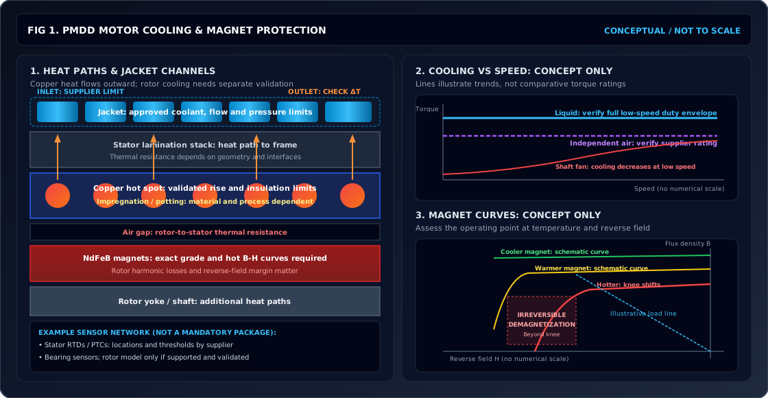
PMDD Motor Thermal Management & Cooling Sizing: Liquid Water Jacket, Forced-Air Convection, and NdFeB Magnet Thermal Limits
Size PMDD motor cooling with a worked flow example. Compare water jackets and forced air, check NdFeB thermal limits, and prepare your cooling RFQ for review.
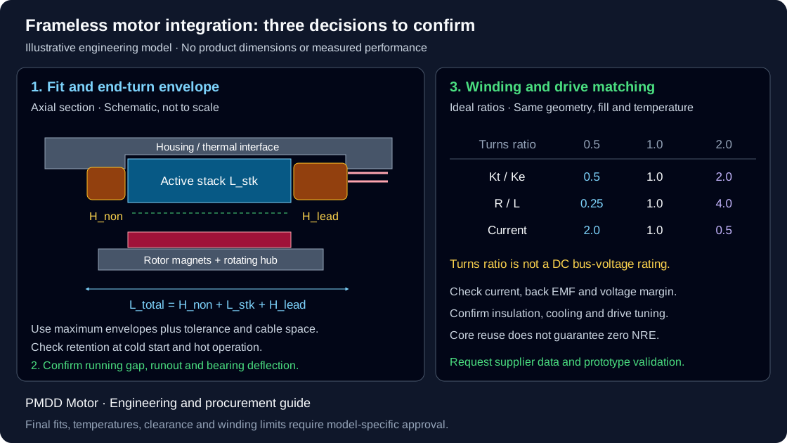
Frameless Torque Motor Integration: Housing Bore Fits, End-Turn Stack, and Winding Adaptation
Plan frameless torque motor integration with housing-fit calculations, end-turn clearance checks, winding trade-offs, and RFQ checklist. Request a CAD review.
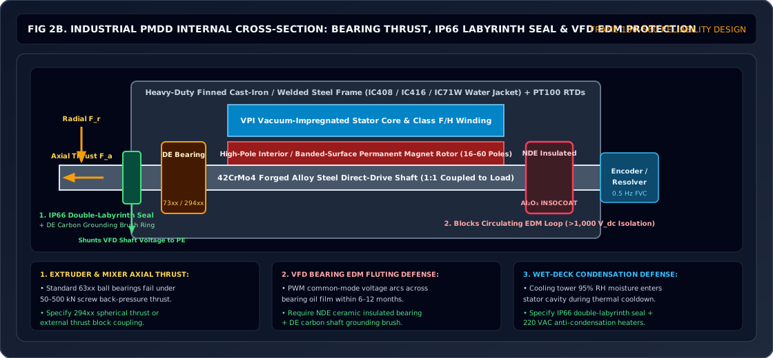
PMDD Bearing Sizing & EDM Protection: Thrust Loads, L10h Life, and VFD Shaft Currents
Size PMDD motor bearings for thrust and L10h life, compare VFD shaft-current protection, and prepare an RFQ with load, lubrication, and commissioning requirements.