
By PMDD Motor · Reviewed

Ball Mill Direct Drive Motor Retrofit Assessment Tool

Screen torque, energy and retrofit constraints.

Retrofit screening tool

Request review

Illustrative defaults. Screening only.

1. Mill geometry & load

1.5–8 m. Nc ≈ 42.3 / √D; ball diameter omitted. Screening approximation.

2–16 m. Expansion assumes steel α = 12 µm/(m·°C) and a 45°C rise.

40–5,000 kW of mechanical output at the shell, not motor nameplate or grid input.

8–35 RPM. 65–82% Nc is an assumed review band, not a process recommendation.

1–3× continuous torque; illustrative demand only. Obtain measured start torque and duration.

2. Energy assumptions

0–8,760 h at the entered shell power. Zero hours gives no operating benefit.

0–1 USD/kWh. Energy charge only; demand charges and taxes excluded.

50–99%. Illustrative default; replace with measured total driveline efficiency.

50–99%. Illustrative combined converter/motor efficiency, not a product rating. Equal/worse is allowed.

3. Project economics

Leave blank if unknown: payback stays N/A. Include equipment, civil work, installation and outage cost.

Default 0: no avoided maintenance assumed. Use audited costs of removed equipment only.

Default 0 excludes unquantified auxiliaries. Add cooling energy, service and other recurring costs.

4. Reported site conditions
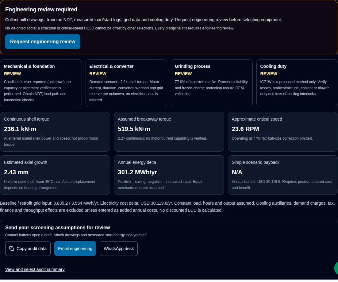
Scenario updated: Engineering review required. Energy delta: 301.2 MWh/year.

Engineering review required

Collect mill drawings, trunnion NDT, measured load/start logs, grid data and cooling duty. Request engineering review before selecting equipment.

No weighted score: a structural or critical-speed HOLD cannot be offset by other selections. Every discipline still requires engineering review.

Request engineering review

Mechanical & foundation

REVIEW

Condition is user-reported (unknown); no capacity or alignment verification is performed. Obtain NDT, load-path and foundation checks.

Electrical & converter

REVIEW

Demand scenario: 2.2× shell torque. Motor current, duration, converter overload and grid reserve are unknown; no electrical pass is inferred.

Grinding process

REVIEW

77.0% of approximate Nc. Process suitability and frozen-charge protection require OEM validation.

Cooling duty

REVIEW

IC71W is a proposed method only. Verify losses, ambient/altitude, coolant or blower duty and loss-of-cooling interlocks.

Continuous shell torque

236.1 kN·m

At entered useful shell power and speed; not pinion motor torque.

Assumed breakaway torque

519.5 kN·m

2.2× continuous; no motor/current capability is verified.

Approximate critical speed

23.6 RPM

Operating at 77% Nc; ball-size correction omitted.

Estimated axial growth

2.43 mm

Uniform steel shell; fixed 45°C rise. Actual displacement depends on bearing arrangement.

Annual energy delta

301.2 MWh/yr

Positive = saving; negative = increased input. Equal mechanical output assumed.

Simple scenario payback

N/A

Annual benefit: USD 30,119.6. Requires positive entered cost and benefit.

Baseline / retrofit grid input: 3,835.2 / 3,534 MWh/yr. Electricity cost delta: USD 30,119.6/yr. Constant load, hours and output assumed. Cooling auxiliaries, demand charges, tax, finance and throughput effects are excluded unless entered as added annual costs. No discounted LCC is calculated.

Send your screening assumptions for review

Contact buttons open a draft. Attach drawings and measured start/energy logs yourself.

View and select audit summary

1. Decision summary: select the evidence path

  • Separate gearless and pinion-direct paths before sizing. Removing a reducer may retain the girth gear; a ring-motor GMD is a separate architecture. ABB architecture evidence.
  • Condition is a starting point. Structural damage creates a hold; reported good condition still requires capacity verification. This is the tool’s conservative screening rule, not a standard certification.
  • Evaluate converter/motor interactions and site grid conditions together. A cooling code or front-end choice cannot establish readiness. IEC application scope.
  • Use equal-output energy comparison and entered project costs. No guaranteed efficiency, outage, service life or payback is established by public evidence for this site.
Architecture comparison — qualitative engineering scope, not a price or performance guarantee On small screens, scroll horizontally.
Decision dimensionProposed trunnion/shaft PM drivePinion-direct PM driveReducer refurbishment
Torque path1:1 shell coupling, if structurally feasibleMotor → retained pinion/girth gearExisting geared path
Critical evidenceAdded mass, bending, reaction support, alignmentGear rating, ratio, bearing duty, load sharingInspection and remaining component life
Maintenance boundaryRemoved gear duties may disappear; bearings and cooling remainGirth gear lubrication and alignment remainGear oil and wear duties remain
Energy comparisonObtain total grid-to-shell duty efficiencyInclude retained gear and converter lossesMeasure repaired baseline at equal output
Cost and outageUnknown until scope, rigging and site plan existUnknown until interfaces and gear condition verifiedObtain comparable repair scope and warranty

Evidence scope: ABB — Ring-geared mill drive system; ABB — Gearless mill drives; ANSI/AGMA 6014-B15 — Gear power rating for cylindrical shell and trunnion supported equipment. Public sources checked 2026-11-01; site acceptance values remain to be confirmed.

Compare gearbox replacement architectures when the retained gear path is your main decision.

2. Five workstreams for an engineering audit

5-phase audit roadmap
  1. Survey & load data
  2. Discipline reviews
  3. Cost & acceptance plan

Five workstreams: mechanical/civil, electrical, process protection, thermal/environmental and commercial. They run together; a failed safety requirement blocks selection.

  • Mechanical: NDT, load path, bearing support and foundation review.
  • Electrical: grid study and motor/converter torque-time capability.
  • Process: operating envelope and approved charge-protection functions.
  • Thermal: losses, ambient duty, cooling utilities and interlocks.
  • Commercial: comparable scope, costs, outage and acceptance evidence.
Required evidence and release responsibility On small screens, scroll horizontally.
WorkstreamCollectResolve before selectionReviewer
Mechanical/civilGA drawings, NDT, runout, bearing and foundation recordsLoad path, support, fatigue and dynamic responseMill OEM and structural engineer
ElectricalVoltage, grid fault level, transformer data, motor/start logsTorque-time capability, harmonics, insulation and protectionDrive supplier and power systems engineer
Process/protectionCharge behaviour, liner/media data, product specificationOperating range, charge detection and validated safe stopProcess and functional safety team
Thermal/environmentAmbient, altitude, cooling utilities, dust and washdownFull-duty heat rejection, enclosure and interlocksMotor/cooling supplier
CommercialEnergy and maintenance records, quotes, outage planComparable installed scope and acceptance planPlant owner and procurement

3. Structural boundaries: inspect before attaching mass

Removing a gearbox changes the load path; it does not prove lower foundation fatigue. Check static loads, transients, modal response, anchor condition and bearing arrangement. Gear-mesh excitation depends on tooth counts and shaft speed; no measured vibration spectrum is available for this proposed retrofit.

Structural evidence path
  1. Drawings & NDT
  2. Loads & modal review
  3. Support design approval

A conceptual review flow. No vibration reduction or allowable runout is inferred.

First-principles checks — examples, not component acceptance limits On small screens, scroll horizontally.
CheckRelation and unitsWorked example / limitation
Shell torqueT = 9550 × P(kW) / n(RPM), N·m450 kW / 18.2 RPM → 236.1 kN·m; no acceleration inertia included
Axial expansionΔL = α × L × ΔTα = 12 µm/(m·°C), ΔT = 45°C: 5 m → 2.7 mm; 12 m → 6.48 mm
Reaction forceF = T / r, N with torque in N·m and perpendicular arm in m200,000 N·m / 1.5 m → 133.3 kN, before design load combinations
Bearing/supportOEM load and lubrication analysisUnknown: motor mass, journal bending, start lubrication and axial freedom

Equations follow rotational power, linear expansion and static moment balance. The tool assumes uniform steel temperature; actual movement depends on fixed/floating bearings and coupling geometry. Inspect defects and obtain site-specific structural calculations; no generic shock factor, oil pressure or journal tolerance is supplied.

4. Converter interfaces and bearing currents

Converter switching, cable layout and grounding affect machine insulation and shaft-current paths. Review the complete motor/drive system. Bearing insulation, grounding and filtering are engineering options requiring coordination; this page does not prescribe a universal threshold or bearing arrangement.

Converter compatibility evidence
  1. Motor + converter data
  2. Cable & current paths
  3. Coordinated mitigation

Specify voltage class, cable length and manufacturer limits before selecting grounding, bearings or output filters.

Interface review checklist On small screens, scroll horizontally.
InterfaceEvidence requestedPossible response to evaluate
InsulationTerminal peak voltage, rise time, cable length and dutyCompatible insulation system and output filtering
Shaft currentsBearing type, current path and grounding layoutInsulated/hybrid bearings or grounding provisions
EMC and bondingCable screen termination and equipotential bonding planCoordinated installation and commissioning measurements

Evidence scope: IEC TS 60034-25:2022 — AC machines used in power drive systems. Public sources checked 2026-11-01; site acceptance values remain to be confirmed.

5. Frozen charge: request validated protection

A charge that adheres to the shell after a stoppage can create a dropped-charge hazard. ABB documents angle and dynamic-torque monitoring as part of mill protection. Detection is different from removal: a frozen-charge alarm does not authorize automatic rocking or a restart.

Charge protection responsibility
  1. Identify charge hazard
  2. OEM protection review
  3. Validated site procedure

Concept only. No trip angle, rocking amplitude, timing or controller program is provided. Inhibiting inverter pulses alone is not a demonstrated safe stop.

Ask for the approved sensing, stopping, alarm, recovery and proof-test procedure. Include loss of supply, sensor failure, rollback and stored charge energy. An unvalidated release function is a reason to hold commissioning.

Evidence scope: ABB — Mill application features (white paper); OSHA 29 CFR 1910.147 — Control of hazardous energy. Public sources checked 2026-11-01; site acceptance values remain to be confirmed.

6. Retained gears and dual-pinion sizing

The tool calculates total shell torque. For a retained ratio i = n_pinion / n_shell and gear efficiency η_g, total pinion torque is approximately T_shell / (i × η_g). With two pinions an equal split is only a starting assumption; load imbalance and transients require separate ratings.

Pinion sizing path
  1. Shell torque demand
  2. Ratio, losses & split
  3. Per-drive duty check

Active load sharing is a documented drive function, not an assumed precision guarantee. Verify gear loads and fault responses.

Request gear condition/rating, torque split, synchronization architecture, torsional study and degraded-operation behaviour. No universal communication latency, preload bias or load-sharing accuracy is established.

Evidence scope: ABB — Ring-geared mill drive system; ANSI/AGMA 6014-B15 — Gear power rating for cylindrical shell and trunnion supported equipment. Public sources checked 2026-11-01; site acceptance values remain to be confirmed.

7. Grid quality, starting duty and stopping

Electrical release path
  1. Grid & duty evidence
  2. Protection coordination
  3. Site acceptance tests

AFE, multipulse and other front ends require a system study. No fixed current percentage, bus clamp or automatic stator-shorting design is selected here.

Electrical unknowns that prevent an automatic pass On small screens, scroll horizontally.
QuestionRequired evidenceDecision limit
Starting capabilityMotor torque/current map, inertia, start duration and frequency; converter limitsAssumed breakaway factor is a demand, not a capability check
HarmonicsPCC definition, grid strength, background distortion and applicable criteriaDrive THDi alone cannot demonstrate PCC compliance
Supply loss/rollbackBack-EMF, kinetic/potential energy, braking duty and failure analysisA PM rotor can generate voltage; no universal braking circuit is safe by default
Maintenance isolationHazardous-energy procedure, stored-energy control and isolation verificationPowered holding or a control stop is not energy isolation

Evidence scope: IEEE 519-2022 — Harmonic control in electric power systems; IEC TS 60034-25:2022 — AC machines used in power drive systems; OSHA 29 CFR 1910.147 — Control of hazardous energy. Public sources checked 2026-11-01; site acceptance values remain to be confirmed.

8. Cooling: method is not capacity

At low shaft speed, a shaft-driven fan may not provide the required heat rejection. Independent air or liquid cooling can address this, subject to a supplier thermal rating. For a fixed fan geometry the affinity relations approximate airflow ∝ speed and fan power ∝ speed³; airflow does not follow the cube law.

Thermal verification
  1. Losses + ambient duty
  2. Cooling utility design
  3. Thermal test + interlocks

Cooling designation and ingress protection are separate. No flow, noise, IP or full-torque capability is inferred from a selection.

Cooling alternatives — confirm the actual manufacturer designation On small screens, scroll horizontally.
OptionUtility / duty evidenceRisks and mitigation
Liquid arrangement, e.g. IC71WLoss map, inlet temperature, flow, water quality and pressure dropLeaks, corrosion or utility loss; specify monitoring and safe loss-of-cooling response
Independent blower, e.g. IC416Air path, ambient, altitude, filter pressure drop and blower supplyDust, clogging and auxiliary failure; review filtration and monitoring
Shaft-driven fanMeasured thermal capability at required low-speed torqueDo not assume high-speed catalogue rating applies; derate or choose another arrangement

Evidence scope: IEC 60034-6:1991 — Methods of cooling (IC Code); IEC TS 60034-25:2022 — AC machines used in power drive systems. Public sources checked 2026-11-01; site acceptance values remain to be confirmed.

9. Process limits and critical-speed interpretation

From particle force balance, ω²R = g gives Nc ≈ 42.3 / √D in RPM. A finite media diameter changes the radius to (D − d)/2. The simplified tool omits d, so its critical-speed hold is approximate; operation below it is not proof of a suitable or safe process speed.

Process trial evidence
  1. Feed, liners & media
  2. OEM operating envelope
  3. Controlled plant trial

The 65–82% review band is an editorial screening assumption. Do not set speed from this band or from Bond Work Index alone.

Validate product size, throughput and specific energy at comparable feed hardness, filling, media and liner condition. Variable speed can support tuning; induction-motor drives may also offer it. No automatic power saving or throughput gain is credited by this tool.

Evidence scope: Metso — Correct liner selection, optimal mill efficiency; ABB — Ring-geared mill drive system. Public sources checked 2026-11-01; site acceptance values remain to be confirmed.

10. Reproducible scenarios, not field results

These are hypothetical calculations using the same tool model. No customer deployment, measured vibration improvement or commercial return is claimed.

Ball mill retrofit assessment software showing 236.1 kN·m shell torque and 301.2 MWh annual scenario energy delta
Original software execution, 1 November 2026: 450 kW, 18.2 RPM, 7,500 h/year, 88% → 95.5% assumed efficiency. Reproduce with Reset defaults. Software arithmetic only, not a physical test or customer result.

A. Default energy comparison

450 kW shell output, 18.2 RPM, 7,500 h/yr, 88% baseline and 95.5% retrofit efficiency.

Continuous torque: 236.1 kN·m. Energy delta: 301.2 MWh/yr, worth USD 30,120 at USD 0.10/kWh.

Next: validate both efficiencies; payback is N/A until a project cost is entered.

B. Adverse efficiency scenario

Same 450 kW and 7,500 h/yr, with 92% baseline and 90% retrofit efficiency.

Input rises by 81.5 MWh/yr. With zero maintenance credit, annual benefit is negative and payback is N/A.

Next: compare repair and inspect the assumed efficiency boundary.

C. Constraints override economics

Use default energy inputs but report severe trunnion/foundation damage, or set 8 m diameter and 20 RPM.

Severe damage creates HOLD. The speed example is about 133.7% of approximate Nc and also creates HOLD.

Next: resolve defects and the OEM operating envelope before selection, regardless of energy delta.

Risk and recovery decisions — no universal exclusion threshold On small screens, scroll horizontally.
RiskDecision consequenceMinimum next step / alternative
Structural damage or unknown capacityHold selection where severe defects are reportedObtain NDT and structural review; consider repair before conversion
Poor or unverified energy benefitNo energy-led investment case is establishedMeasure equal-output input; compare reducer refurbishment
Cooling, grid or rigging mismatchProject scope and cost remain unresolvedSurvey utilities and lifting access; compare retained-gear options
Low duty or short remaining asset lifeSimple payback alone may misleadUse expected operating life and full cost scope in a separate investment review

11. Reconcile the financial boundary

For equal useful shell power P and annual hours h: E_grid = P × h / η / 1000 in MWh. Energy saving is E_base − E_retrofit; a negative value is an increase. Annual benefit = energy delta × 1000 × tariff + entered maintenance saving − entered added annual costs. Simple payback = entered installed cost / positive annual benefit.

Default scenario reconciliation — USD, constant output, no measured business data On small screens, scroll horizontally.
ItemDefault model valueKnown / unknown and next action
Baseline / retrofit input3,835.2 / 3,534 MWh/yrCalculated from illustrative efficiencies; measure at matching duty
Annual electricity cost deltaUSD 30,120/yrCalculated at USD 0.10/kWh; no demand-charge effects
Maintenance / added costUSD 0 / USD 0 per yearNo credit assumed; unknown auxiliary costs must be entered
Installed cost and paybackUnknown / N/AGet comparable installed quote including civil work, rigging and outage
Discounted life-cycle costNot calculatedAdd discount rate, replacements, residual value, taxes and risk separately

The model uses constant shell power for all entered hours, not a load-duration curve. Do not count maintenance savings for retained gears. Zero hours suppresses operating benefits; zero tariff removes only energy-cost benefit. Unknown project cost remains unknown. No universal payback window is supported.

12. Decision questions

Tool & sizing

What does this assessment actually decide?

It estimates shell torque, critical-speed fraction, thermal growth and equal-output energy scenarios. It identifies review needs and holds. It cannot approve a trunnion, foundation, converter, cooling system or installation.

Should I enter motor nameplate power?

Enter useful mechanical power at the shell. Motor nameplate rating and measured grid input are different boundaries. If shell power is unknown, request a load and efficiency review rather than treating the nameplate as measured output.

Is the critical-speed formula exact?

Nc ≈ 42.3 / √D is a screening approximation in RPM with D in metres inside liners. A ball-centre correction uses D − d, where d is media diameter. Liner and media geometry and the OEM process envelope must be checked before setting speed.

Does a 2.2× torque factor prove a 220% current requirement?

No. The factor is an assumed shell demand. The current needed depends on the motor torque/current map, control, saturation, gear ratio, acceleration and duration. Obtain both motor and converter torque-time/current limits.

Mechanical

Why does a severe condition produce HOLD?

A reported severe trunnion or foundation defect must be resolved independently. Energy benefits or a preferred cooling selection cannot offset it. Request structural and mill OEM review before equipment selection.

Does no known damage establish trunnion capacity?

No. Added rotor mass, bending, reaction torque, alignment, bearing lubrication and fatigue require drawings, inspection and calculations. User-reported condition is not an NDT result or capacity verification.

Can shell torque be used to size a pinion motor?

Not directly. For a retained gear ratio i = n_pinion / n_shell, a first estimate is T_pinion = T_shell / (i × gear efficiency). Confirm transient duty and dual-pinion load sharing separately.

Is a shaft-mounted PM motor the same as a wrap-around GMD?

No. A large ring-motor GMD and a proposed shaft/flange-mounted PM arrangement have different electromagnetic and structural interfaces. Evidence for a ring motor does not establish availability of a shaft-mounted retrofit.

Electrical & safety

Does an AFE automatically meet IEEE 519?

No. Evaluate the applicable voltage and current distortion criteria at the PCC using the site system data and agreed measurement method. A drive-terminal THDi figure is insufficient to demonstrate plant compliance.

Which bearing-current measures are mandatory?

There is no universal component recipe established by this page. Review motor/converter interactions, grounding, cable layout, filters and bearing arrangements with the manufacturers using IEC TS 60034-25 and the applicable motor voltage class.

Can I use the page to set frozen-charge trip angles or rocking?

No. Charge detection, controlled stopping and any removal function require a validated OEM procedure and site risk assessment. No trip angle, reversal torque, pulse-blocking time or automatic restart instruction is provided.

Can electronic holding torque isolate a mill for maintenance?

No. Use the applicable hazardous-energy procedure, isolate energy sources, control stored charge energy and verify isolation before work. A competent engineer must specify physical restraint and its verification; a powered holding function is not an isolator.

Thermal & economics

Does selecting IC71W or IC416 guarantee cooling?

No. The code describes a method. Confirm full-duty losses, ambient, altitude, water or air requirements and failure interlocks. Thermal rating and enclosure ingress protection require separate evidence.

What happens if retrofit efficiency is lower?

The tool accepts the scenario and shows a negative energy delta, meaning higher grid input for equal shell output. Compare refurbishment and validate assumptions before using a payback estimate.

Why is payback N/A?

Payback requires a positive entered installed cost and positive annual benefit. Unknown or zero cost, zero hours, zero benefit or a net loss returns N/A. No maintenance saving or capital cost is invented to fill missing data.

What should an RFQ include?

Send mill and interface drawings, condition reports, shell-power basis, measured speed/start logs, existing gear ratio, grid data, cooling conditions, duty and commercial scope. Ask suppliers to identify unverified assumptions and acceptance evidence.

13. Prepare a reviewable retrofit request

Use the tool’s copy or email action to share assumptions. Add mill GA/interface drawings, inspection records, measured speed/start/load logs, existing gear ratio, grid data, duty and cooling conditions. If values are missing, request a data-gap review first.

Ask the supplier to confirm the proposed architecture, load path, torque-time capability, cooling duty, protection scope, comparable installed cost and acceptance tests in writing. Manufacturing availability, certification, lead time and performance remain unconfirmed until supported by project evidence.

Email the retrofit review requestReturn to the screening tool
PMDD Motor · WhatsApp Engineering Support