
Published · reviewed
Ball Mill Direct Drive Motor Gearbox Replacement
Compare pinion-direct and 1:1 trunnion PM concepts. Enter useful shell power and speed to estimate torque and an energy scenario before requesting an engineering review.
Torque & energy tool
Instant estimates; defaults are hypothetical.
Concept only: gearbox, pinion and girth gear removed; trunnion feasibility unverified.
30–3,500 kW; mechanical output, not motor nameplate or electrical input.
8–35 RPM screening range; confirm the mill operating envelope.
1–3×; default 2.2 is a scenario, not a verified starting duty.
Energy & reaction assumptions · 7500 h/year · 88% → 95.5%
0–8,760 h; assumes constant useful shell power while running.
50–100%; electrical supply to useful mill-shell power.
50–100%; include VFD, motor and retained gears; scenario only.
0.4–3.5 m; effective perpendicular lever arm, not bolt spacing.
Continuous motor torque
132,639 N·m
18 RPM; shell torque 132,639 N·m. Ideal 1:1 mechanical interface.
Assumed peak starting torque
291,806 N·m
2.2× continuous; required duration, acceleration and starts/hour remain unverified.
Idealized reaction resultant
243.2 kN
F = T_peak / 1.2 m. One equivalent lever arm; no bolt sharing, bending, dynamic or anchor design model.
Scenario annual energy reduction
167.33 MWh/year
7.85% relative reduction; 7.5 percentage-point efficiency change. Negative means increased consumption.
Screening limits: Not a motor rating, anchor design, protection setting or guaranteed saving. Confirm peak duration, cooling and structural loads with the mill and drive suppliers.
Energy model: P_shell × hours × (1/η_baseline − 1/η_retrofit) / 1,000. Both efficiencies cover supply to shell, including retained mesh losses. Separate auxiliary power, variable load and throughput changes are excluded.
Annual electrical input: baseline 2,130.68 vs retrofit 1,963.35 MWh. Replace defaults with measured values before budgeting.
Read formulas, evidence and limitsView or manually copy the inquiry summary
1. Decide what is being replaced
Retain a viable gear train
Pinion-direct removes the reducer while retaining the pinion and girth gear. Their condition and lubrication remain decision gates.
Evidence and scopeSeparate PM concepts from ring GMDs
A shaft-mounted PM retrofit and a wrap-around ring GMD have different interfaces and electrical arrangements. Treat them as separate engineering options.
Evidence and scopeRequire a maintenance safety plan
Creeping and electronic positioning do not replace energy isolation and stored-energy restraint before exposed maintenance.
Evidence and scopeDecision rule: compare reducer renewal first, investigate pinion-direct if the retained gear train is suitable, and investigate a 1:1 PM interface only after the mill designer confirms structural feasibility. This is an engineering screening sequence, not a supplier recommendation.
2. Compare ball mill direct drive architectures
Baseline to audit: motor, reducer, couplings and open-gear system. Measure supply-to-shell losses rather than assuming a fixed efficiency.
Reducer removed. Girth gear condition, mesh losses, alignment and spray lubrication remain in scope. Single-pinion calculator only.
Gear train removed. Load path, bearing support, thermal travel and reaction restraint need a new design. This shaft/flange PM concept is distinct from a large wrap-around ring GMD.
Conceptual power paths, not installation drawings. Arrow direction shows driving power flow. No efficiency, outage or supplier capability is certified by these diagrams.
| Decision dimension | 1:1 trunnion PM concept | Pinion-direct PM concept | Reducer renewal alternative |
|---|---|---|---|
| Removed equipment | Reducer, pinion and girth gear | Reducer; existing pinion and girth gear remain | Failed or obsolete reducer components |
| Motor speed | Same as shell RPM | Shell RPM × tooth ratio | Existing drivetrain speed |
| Structural gate | Trunnion, support, bearings, mass and flange load path | Shaft interface, gear contact, pedestal and coupling | Alignment, support and original duty |
| Maintenance scope | New motor, drive, supports and cooling | Motor/VFD plus retained open-gear maintenance | Reducer lubrication, gears, seals and bearings |
| Best next investigation | Mill-OEM structural feasibility review | Gear-condition report and shaft survey | Overhaul scope and installed repair quote |
| CAPEX / outage | Unknown; obtain engineered installed quote | Unknown; no universal cost advantage or duration | Unknown; include failure risk and spare availability |
ABB documents ring-geared drives with and without reducers. That supports the architecture distinction, not availability or performance of a particular PM motor. ABB ring-geared system. The ABB ring GMD brochure describes an excited ring machine, not the trunnion PM concept modeled here.
Comparing a gearbox renewal with a retrofit? Request a drawing and load review before committing to an architecture.
3. Reproduce the motor torque and energy calculation
These equations follow mechanical power balance and a constant-efficiency energy balance. The rounded constant 9,550 follows 60,000/(2π). No ore-grinding power, critical speed, acceleration torque or equipment rating is predicted.
| Output | Equation | Boundary |
|---|---|---|
| Shell torque, N·m | T_shell = 9,550 × P_shell[kW] / n_shell[RPM] | Useful mechanical shell output; not feeder kW |
| Pinion motor speed, RPM | n_motor = n_shell × i | i = girth teeth / pinion teeth; single pinion |
| Motor torque, N·m | T_motor = T_shell / (i × η_mesh) | Trunnion: i=1, η_mesh=1; pinion: editable mesh loss |
| Assumed peak torque, N·m | T_peak = K × T_motor | K is a scenario; duration, acceleration and repeat duty unknown |
| Ideal reaction resultant, kN | F = T_peak / r[m] / 1,000 | One perpendicular effective arm; no anchor design or load sharing |
| Annual electrical input, MWh | E = P_shell × hours / η_total / 1,000 | Total supply-to-shell efficiency includes VFD and retained gears |
| Annual energy reduction, MWh | ΔE = E_baseline − E_retrofit | Same useful load and hours; separate auxiliaries excluded |
| Relative energy reduction, % | 100 × (1 − η_baseline / η_retrofit) | Different from the percentage-point efficiency change |
Loss boundaries matter: the mesh efficiency input affects shaft torque only. Do not subtract that loss again from an already complete supply-to-shell efficiency. A negative energy reduction is a valid adverse scenario. Use a measured duty-cycle integration when shell load varies.
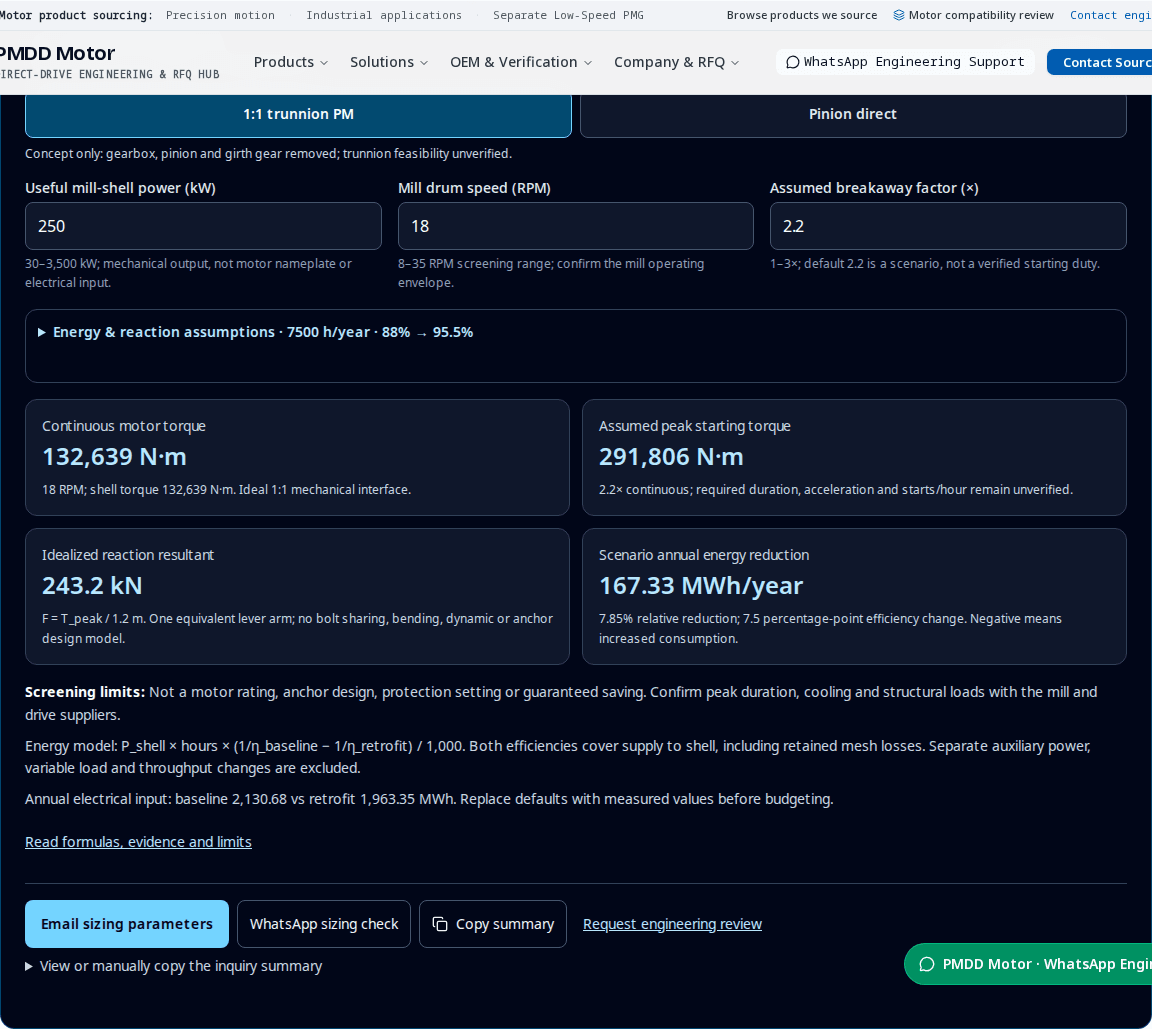
Original software execution captured 31 October 2026. Inputs: trunnion concept, 250 kW, 18 RPM, factor 2.2, lever arm 1.2 m, 7,500 h/year, efficiencies 88% and 95.5%. Rounded outputs: 132,639 N·m continuous, 291,806 N·m assumed peak, 243.2 kN idealized reaction and 167.33 MWh/year scenario reduction. This screenshot verifies the software arithmetic; it is not a physical test, customer result or equipment rating. Reproduce these inputs in the tool above.
4. Know what remains unverified
| Item | Known on this page | Unknown / evidence to obtain |
|---|---|---|
| Power and speed | Editable mechanical scenario inputs | Actual shell duty, measurement uncertainty and operating envelope |
| Efficiency | 88% baseline; 95.5% trunnion or 93% pinion scenario | Measured supply-to-shell efficiencies and auxiliary loads |
| Starting duty | Editable 2.2× default; no duration claim | Torque-time curve, acceleration, starts/hour and VFD current capability |
| Mechanical fit | Conceptual power path only | Drawings, support loads, bearings, fatigue and thermal travel |
| Cooling and protection | Require an application-specific review | Thermal curves, interlocks, insulation and bearing-current strategy |
| Commercial evidence | No price, payback, delivery or outage guarantee | Named supplier/model, installed quotation and acceptance documents |
5. Work through three hypothetical scenarios
Illustrations only; no customer installation, measured savings or payback is claimed. Reproduce with the stated inputs. Peak duration and supplier feasibility are unknown in every row.
| Scenario / inputs | Calculation | Result | Decision / limitation |
|---|---|---|---|
| A: trunnion, 250 kW, 18 RPM, K=2.2 | 9,550 × 250 / 18; then ×2.2 | 132,639 N·m continuous; 291,806 N·m peak | At r=1.2 m, ideal resultant 243.2 kN; structural feasibility unverified |
| B: pinion, 250 kW, 18 RPM, i=8.5, mesh=97.5%, K=2.2 | n=18×8.5; T=132,638.9/(8.5×0.975) | 153 RPM; 16,005 N·m continuous; 35,210 N·m peak | Retained mesh adds torque demand; inspect gears before selecting motor |
| C: energy sensitivity, 250 kW; baseline 88% | ΔE = 250×7,500×(1/0.88−1/η)/1,000 | η=95.5%: 167.33 MWh; η=93%: 114.55 MWh; η=85%: −75.20 MWh | Illustrative energy only; a worse retrofit efficiency increases consumption |
6. Reject unsuitable or unsafe conversion paths
| Risk | Required review / mitigation | Alternative if unresolved |
|---|---|---|
| Frozen or adhered charge | Mill-specific detection and recovery functions verified with OEM; do not apply generic rocking angles | Stop the retrofit decision until an approved recovery procedure exists |
| Unexpected motion during maintenance | Approved isolation, stored-energy restraint and verification; energized holding is not isolation | Retain or redesign the approved mechanical restraint/access arrangement |
| Trunnion or anchor overload | Structural analysis of torque, mass, bending, fatigue, support and fault cases | Pinion-direct assessment or reducer renewal |
| Retained gear wear / misalignment | Gear-condition survey, tooth contact, alignment and lubrication review | Repair/renew the gear train or investigate a different architecture |
| Low-speed thermal overload | Model-specific torque-speed thermal curve with actual cooling/ambient and interlocks | Derate or change cooling/motor design |
| Motor/VFD mismatch | Peak current-time envelope, feedback, voltage, insulation and bearing-current review | Matched drive package or retain the present motor with renewed reducer |
| Cost and process mismatch | Compare installed quotes, shutdown exposure and measured energy per tonne | Repair first if incremental benefit cannot justify conversion |
ABB lists frozen-charge and positioning features on specific mill drive systems; their presence must be confirmed for an offered package. Application-feature source. For exposed maintenance, use the site energy-control plan and verified restraints; see the scope of OSHA 1910.147(d)(5)–(6).
7. Specify thermal, electrical and mechanical acceptance
Mechanical
Request interface drawings, support loads, shaft/bearing checks, alignment limits and thermal-travel provision. A torque arm or flange is an engineered load path, not a universal retrofit accessory.
Thermal / electrical
Request the offered motor and drive torque-speed/current-time curves, site derating, cooling-loss interlocks and insulation/grounding design. Do not select water cooling from a fixed kW threshold.
Documents
Agree applicable standard editions and acceptance criteria in the contract with the responsible engineers. A referenced standard or OEM publication is not certification of a sourced PMDD motor.
8. Build the business case from measured inputs
At the hypothetical 250 kW / 7,500 h case, 88% → 95.5% efficiency reduces input energy by 167.33 MWh/year, or 7.85% relative, for the same shell work. At an assumed $0.09/kWh tariff this is about $15,059/year before auxiliary power, maintenance and production effects. The efficiency difference is 7.5 percentage points. These are calculations, not a price or savings forecast.
| Decision input | Reproducible treatment | Evidence needed |
|---|---|---|
| Incremental installed cost | Retrofit installed cost minus the realistic repair/renewal alternative | Itemized equipment, engineering, civil work, commissioning and outage quotes |
| Annual electricity benefit | ΔE[MWh] × 1,000 × tariff[$/kWh], less added auxiliary energy cost | Comparable load records, tariff schedule, cooling/pump/blower consumption |
| Annual maintenance benefit | Avoided reducer costs minus new motor/VFD/cooling and retained-gear costs | Site work orders, lubricant consumption and vendor service scope |
| Simple payback | Incremental installed cost / annual net benefit | Unknown until cost and benefit are established; no positive benefit means no finite positive payback |
| Long-term appraisal | Discount cash flows using site assumptions and sensitivity cases | Discount rate, tariff exposure, spares, failures, residual value and production constraints |
9. Move from screening to a verified scope
- 1. Measure
Record feeder load, loss boundaries, RPM, charge, starts and throughput; establish useful shell duty.
- 2. Survey
Inspect gears and foundations; obtain trunnion, shaft, bearing and space-envelope drawings.
- 3. Engineer
Agree architecture, structural checks, motor/VFD duty, cooling, protection, isolation and installed scope.
- 4. Validate
Use approved factory/site acceptance plans, then compare energy at matched throughput and operating conditions.
10. Sources and evidence boundaries
Review cycle: every six months or when cited guidance changes. Primary sources checked 31 October 2026. OEM examples describe their own systems and do not establish endorsement, supply capability or PMDD Motor field results. Efficiency defaults and numerical examples are disclosed assumptions derived using section 3.
- ABB — Ring-geared mill drive system
Gearbox-free ring-geared configurations and application-control features. Does not establish PMDD product availability or site savings.
- ABB — Gearless mill drives, pp. 2–3
Ring GMD construction and excitation. This large wrap-around system is not evidence for a shaft-mounted permanent magnet retrofit.
- OSHA — 29 CFR 1910.147, (d)(5)–(6)
US general-industry hazardous-energy isolation, stored-energy control and verification. Apply the rules and mill procedures for the site jurisdiction.
11. Ball mill gearbox replacement FAQ
Inputs & sizing
Which power belongs in the calculator?
Use useful mechanical power at the mill shell. Motor nameplate kW is a rating; electrical feeder kW includes upstream losses. If only feeder power is available, establish a defensible loss balance with the engineering team before entering shell power.
How does pinion-direct motor speed differ from mill speed?
Motor speed equals mill RPM multiplied by the girth-to-pinion tooth ratio. At 18 RPM and 8.5:1, the pinion motor runs at 153 RPM. Shaft torque includes the assumed retained mesh loss; the shell still turns at 18 RPM.
Is the 2.2× breakaway factor a motor overload rating?
No. It is an editable scenario multiplier. Actual breakaway, acceleration, overload duration, repeat starts and thermal recovery require a load record and written motor/VFD verification. The calculator does not prove a 30-second or 60-second overload capability.
Can this tool size a dual-pinion conversion?
No. It models one driving motor and one retained mesh. Dual-pinion sharing, transient imbalance, fault torque and synchronizing control require a coordinated mechanical and electrical study. Send both driveline drawings for a manual review.
What happens if my inputs are blank or outside the ranges?
The tool hides numerical results and parameter-export links, shows the fields to correct, and keeps a manual engineering-review link available. Reset restores the illustrative defaults. The input ranges define this screening tool, not a product catalogue.
Mechanical choice
Does removing the gearbox remove the girth gear?
Only the 1:1 trunnion concept shown here removes both. A pinion-direct concept retains the girth gear and pinion, so mesh alignment, tooth condition and lubrication remain maintenance obligations. Compare the power-path diagram and architecture table before choosing.
Is trunnion PM direct drive the same as a ring GMD?
No. Here it means a candidate shaft/flange permanent magnet machine connected 1:1 to the trunnion. ABB’s cited ring GMD mounts rotor poles on the mill and uses a surrounding stator with a separate excitation system. Its field record cannot validate a PM shaft-motor retrofit.
Can the existing trunnion carry the retrofit?
That is unknown until the mill OEM or responsible designer checks torque, added mass, bending, fatigue, bearings, support stiffness and interface stresses. A flange that fits dimensionally does not establish structural suitability. Retaining the pinion train or renewing the reducer may be the practical alternative.
Can the reaction result size anchor bolts?
No. F = T/r is one idealized tangential resultant. It excludes bolt-group geometry, unequal sharing, anchor tension, bending, dynamic amplification, concrete capacity and fault loads. A civil/structural designer must calculate the actual support and anchor loads.
Controls & operation
Does a PM motor automatically provide frozen-charge protection?
No. ABB documents such functions for particular mill drive systems; availability on a proposed PM motor/VFD package needs explicit confirmation. Detection logic, motion limits and recovery procedures must be approved for the exact mill. This page provides no commissioning thresholds.
Can energized holding torque secure the mill for liner work?
Energized holding torque is not an energy-isolation method. Before exposed maintenance, follow the approved site isolation procedure, restrain hazardous stored mechanical energy and verify the safe state. Use the mill-specific restraint and access plan; creeping or positioning capability does not authorize personnel entry.
How should cooling be selected?
Request a verified torque-speed thermal envelope at the actual ambient, altitude, dust and cooling-water conditions. Low-speed cooling cannot be inferred from nameplate kW or a fixed power threshold. Confirm independent blower or liquid-cooling arrangements, auxiliary consumption and loss-of-cooling interlocks for the offered model.
Energy & economics
Are the efficiency defaults measured performance?
No. The 88% baseline and 95.5% trunnion / 93% pinion retrofit values are hypothetical total supply-to-shell efficiencies. They include motor, drive and retained transmission losses. Replace them with consistently measured values; separate auxiliaries and changing throughput need an expanded model.
Why can the energy reduction be negative?
If assumed retrofit efficiency is below the baseline, the same shell work needs more electrical input. A negative reduction flags that scenario rather than concealing it. Zero operating hours or equal efficiencies produce zero annual reduction.
Can this page promise a payback or outage duration?
No. Obtain installed quotations for the current repair option and retrofit, lost-production exposure, tariff, auxiliary loads and maintenance records. Payback needs the incremental installed cost and verified annual net benefit; no universal installation duration or return is established here.
Procurement
What should I send for a useful RFQ?
Send mill and shaft drawings, useful shell load or a measured electrical load balance, operating speed, gearbox and tooth ratios, start/stop duty, supply voltage, ambient/cooling conditions, outage constraints and destination. Request model-specific curves, interface drawings, protection scope and an itemized installed quotation.
12. Turn the scenario into an engineering request
Copy or email the calculator summary with mill drawings, load records, supply details and outage constraints. Request feasibility, model-specific duty curves, an interface drawing, protection scope and an itemized quotation. If inputs are unknown, start with a nameplate and layout drawing; mark unknowns for manual review.
Related engineering scopes: matched motor and VFD packages, drive compatibility and compliance, and custom interface engineering.
WhatsApp opens the configured site contact. If that channel is unavailable, use the inquiry form or email [email protected]. Supplier, model, ratings, price and delivery require written confirmation.