
PMDD Bearing Sizing & EDM Protection: Thrust Loads, L10h Life, and VFD Shaft Currents
Size PMDD motor bearings for thrust and L10h life, compare VFD shaft-current protection, and prepare an RFQ with load, lubrication, and commissioning requirements.
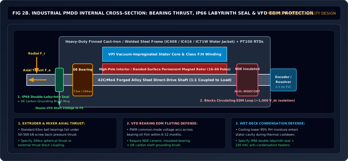
Quick answer: Size PMDD motor bearings from the actual shaft-support arrangement and signed axial/radial load cases, then check fatigue life, static capacity, lubrication, and VFD bearing-current protection separately. An L10h calculation does not predict electrical erosion or guarantee service life. Insulated bearings and shaft grounding are options to evaluate against the complete motor, drive, cable, and driven-machine arrangement.
Reviewed: October 27, 2026 · Global engineering and procurement guidance · Publisher: PMDD Motor. This guide covers industrial rolling-bearing PMDD applications such as cooling towers, mixers, and conveyors. Speed, load, and life values in examples are assumed inputs, not measured product performance. It does not cover magnetic/fluid bearings, approve a bearing part number, or establish compliance with local electrical rules. The selected supplier must confirm the arrangement and acceptance criteria for the project.
Removing a gearbox can move process thrust and bending reactions into the motor bearings when the driven load is supported directly by the motor shaft. External pillow blocks, thrust blocks, and couplings can change that load path. In parallel, a pulse-width modulated (PWM) variable frequency drive (VFD) can create shaft currents in both permanent-magnet and induction machines.
Have a retrofit under review? Send the shaft-support drawing, thrust cases, and VFD details for an application quotation.
The header image is a conceptual arrangement, not a certified motor drawing. Open the full-size bearing and grounding schematic to compare the load path and current path with your proposed layout.
PMDD Mechanical Load Sizing & Inverter EDM Suppression Rules
- L10h = (10^6 / (60 * n)) * (C / P)^p [Basic fatigue rating]
- P = X * Fr + Y * Fa [Use the selected bearing catalogue rules]
- kappa = viscosity at operating temperature / reference viscosity
- Minimum load and shaft-voltage acceptance: supplier/project specific
- Confirm which bearings actually support the process load before calculating motor-bearing reactions.
- Low speed can make lubrication difficult; speed alone does not establish film thickness or EDM risk.
- Coordinate bearing insulation, shaft grounding, protective-earth bonding, and the driven-machine current path.
- Continuous and peak downward/upward axial thrust (Fa) in kN.
- Overhung radial load (Fr) and distance from shaft shoulder (L) in mm.
- Agreed basic and modified rating-life targets and duty-cycle assumptions.
- Inverter carrier frequency (kHz), DC-bus voltage, and maximum cable distance.
- Proposed bearing insulation, shaft grounding, and acceptance-test scope.
1. Mechanical Load Architecture: Absorbing Process Forces Without a Gearbox
In a geared drivetrain, gearbox output bearings or external machine bearings may carry the process loads. After a 1:1 direct-drive conversion, identify the locating bearing, floating bearing, external supports, coupling constraints, and thermal expansion path on a free-body diagram.
Motor torque alone does not define bearing loads. Resolve axial force, radial force, and bending moment into reactions at each bearing for steady operation, startup, braking, reversal, and credible abnormal loads before selecting a frame.
1.1 Axial Thrust Sizing and Aerodynamic / Hydrodynamic Forces
For a vertical fan or mixer, include the weight of the supported rotating assembly and the signed aerodynamic or hydraulic reaction. Define the positive direction on the drawing; do not assume fan thrust always offsets gravity.
W_supported = m_supported * g
Fa_case = signed weight + signed process thrust + other axial reactions
Use newtons for force, kilograms for mass, and approximately 9.81 m/s² for gravitational acceleration. A pressure difference times effective area can provide a pressure-force screen, but duct reactions and momentum flux affect the actual fan assembly thrust. Obtain signed thrust curves from the fan or process-equipment supplier; torque and diameter alone cannot establish the bearing thrust.
Thrust Load Inversion Risks
Startup, coast-down, wind, braking, and process reversal can unload a thrust bearing or reverse its load. Check both load directions and the minimum load throughout those transients.
Possible arrangements include opposed single-direction thrust bearings, a suitable paired angular-contact set, or a separate process thrust block. Preload springs may maintain minimum load but do not by themselves make a single-direction bearing suitable for reverse thrust. Minimum load and preload must come from the selected bearing manufacturer's calculation, including speed, temperature, and thermal growth.
1.2 Overhung Radial Loads and Cantilever Bending Moments
An overhung load creates a bending moment as well as a radial force:
M = Fr * LIllustrative reaction calculation: Assume an 8 kN transverse point load acts 0.20 m outboard of the drive-end (DE) bearing and the non-drive-end (NDE) bearing is 0.30 m behind it. A rigid-shaft, two-simple-support model gives a DE reaction magnitude of 8 * (1 + 0.20 / 0.30) = 13.33 kN and an opposing NDE reaction magnitude of 8 * 0.20 / 0.30 = 5.33 kN. The overhung moment is 8 * 0.20 = 1.60 kN·m. This excludes shaft/rotor weight, axial loads, and housing flexibility.
This explains why applying the external 8 kN directly as each bearing's load is incorrect. Ask the supplier to check shaft deflection, air-gap clearance, housing stiffness, bearing fits, and static load safety as well as fatigue life. A separate support may be preferable to enlarging the motor bearing.
2. ISO 281 Rating Life and the Low-Speed Lubrication Trap
The basic rating life L10h is a fatigue calculation associated with 90% reliability for a population under the stated assumptions. A project may request 100,000 operating hours, but that is a buyer's design target, not a universal requirement of ISO 281. The ISO 281 scope expressly excludes wear, corrosion, and electrical erosion from its life prediction.
2.1 Basic Dynamic Rating Life Formula
Per ISO 281, the basic rating life in operating hours is calculated as:
L10h = [1,000,000 / (60 * n)] * (C / P)^pHere n is speed in RPM, C is the catalogue basic dynamic load rating, and P is the equivalent dynamic bearing load. Use the same units for C and P. The exponent p is 3 for ball bearings and 10/3 for roller bearings. Evaluate variable-duty fatigue using the actual speed/load/time spectrum rather than an arithmetic average load.
A common combined-load expression is P = X * Fr + Y * Fa. The selected bearing catalogue determines the factors, load-ratio branches, and applicability. Thrust bearings, paired sets, and preloaded arrangements may require different rules or an internal load-distribution model. Use bearing reactions, not unresolved process forces.
Reproducible life screen: For an assumed ball bearing with C = 100 kN, P = 10 kN, and n = 100 RPM, the formula gives L10h = 166,667 h. Increasing P to 15 kN at the same speed gives only 49,383 h. A 100,000 h target requires P <= 100 / 600^(1/3) = 11.86 kN. These are arithmetic examples, not supplier bearing selections; static capacity, minimum load, lubrication, and electrical protection remain separate checks.
2.2 The Low-Speed Lubricant Film Problem
Low RPM increases the hours corresponding to a given number of revolutions, which can make basic life look generous. It can also make adequate lubricant film formation more difficult. Speed alone does not prove that a bearing operates in mixed or boundary lubrication.
At the same 90% reliability level, ISO 281 modified rating life can be expressed as:
L10mh = aISO * L10h
kappa = nu / nu1
The actual base-oil kinematic viscosity nu is evaluated at bearing operating temperature; reference viscosity nu1 comes from the bearing manufacturer's method using speed and mean diameter. The life modification factor also depends on contamination and the fatigue load limit. A ratio below 1 flags inadequate viscosity relative to that reference. Modified fatigue life still does not model EDM damage or turn a calculated hour value into a warranty.
3. Comparative Matrix: Bearing Topologies for PMDD Drivetrains
Compare these six options after resolving the load path. None has a universal minimum operating speed, grease grade, or motor power range; capacity and lubrication depend on the selected part and arrangement.
| Bearing Topology | Axial Load Role | Radial / Moment Role | Low-Speed Check | Electrical Protection Option | Selection Boundary |
|---|---|---|---|---|---|
| Deep-Groove Ball Bearing | Combined loads within catalogue limits | Radial support; moment carried through support spacing | Viscosity, minimum load, and clearance | Coated-ring or hybrid versions where available | Do not infer thrust capacity from a fixed percentage of C. |
| Back-to-Back Angular-Contact Pair | Can locate the shaft axially in both directions | Arrangement can resist overturning moment | Preload, thermal growth, and internal load sharing | Confirm insulated or hybrid pair availability | Pair preload and fits must match the duty. |
| Spherical Roller Thrust Bearing | High axial loads in one direction per bearing | Can carry limited combined radial load under catalogue conditions | Minimum axial load and lubrication supply | Supplier-designed insulated bearing or housing | Reverse thrust needs an opposing load path; radial guidance may be separate. |
| Double-Row Spherical Roller Bearing | Combined radial and bidirectional axial loads | Self-aligning radial support | Minimum load, viscosity, and mounting clearance | Coated variants or insulated housing where suitable | Self-alignment is not a substitute for shaft-deflection checks. |
| Cylindrical Roller Bearing | Depends on flange arrangement | High radial capacity | Roller/flange lubrication when carrying axial force | Coated-ring versions where available | NU/N designs can float internally; NJ/NUP arrangements have different locating roles. |
| Hybrid Bearing with Ceramic Rolling Elements | Depends on bearing geometry and catalogue ratings | Depends on geometry, fits, and support span | Lubrication and load limits still apply | Ceramic rolling elements interrupt conductive contact paths | Hybrid construction does not guarantee superior load capacity or a fixed life multiplier. |
4. Electrical Discharge Machining (EDM): The Inverter-Induced Failure Mechanism
PWM drives can produce electrical erosion independently of mechanical fatigue. SKF's bearing-insulation explanation describes electrical microcraters and the frequency-dependent behavior of insulating coatings. Failure timing varies; no fixed number of months follows from the motor type.
PWM winding voltage -- Csr -- rotor / shaft
                                |
                +---------------+---------------+
                |               |               |
               Crf           Cb_DE            Cb_NDE
                |               |               |
                +---------------+---------------+
                                |
                         motor frame / PE

Conceptual capacitive model before bearing-film breakdown.
Grounding devices and driven-machine paths are not shown.
4.1 How High-Carrier VFDs Create Shaft Voltage
PWM phase-to-frame voltages do not sum to zero at every instant. Their average is the common-mode voltage:
Vcom(t) = [VU(t) + VV(t) + VW(t)] / 3For a simplified model with intact insulating lubricant films, winding-to-rotor capacitance Csr couples that voltage to the shaft. Rotor-to-frame capacitance Crf and bearing capacitances form the other branches:
Vshaft ≈ Vcom * Csr / (Csr + Crf + Cb_DE + Cb_NDE)This is an explanatory divider, not an acceptance calculation: grounding contacts, cable impedance, film conduction, and driven-machine bearings change the network. Also distinguish capacitive discharge currents from circulating currents and shaft-grounding currents; one mitigation does not necessarily address every path.
4.2 Low RPM Does Not Establish a Universal Breakdown Voltage
Film thickness and electrical behavior depend on load, geometry, lubricant, temperature, speed, and the excitation waveform. A thin or intermittently conducting film changes the current mechanism; low RPM does not prove that every switching pulse causes an EDM arc. PMDD and induction motors can both be affected. Do not treat 1.5 V as a universal safe limit or a requirement established by this guide.
4.3 Four Damage Indicators to Investigate
- Microcraters or frosting: Electrical discharge can damage rolling-contact surfaces; microscopy helps distinguish the mechanism.
- Lubricant deterioration: Discharges can affect lubricant, but dark grease alone does not establish EDM as the cause.
- Fluting: Repeated current passage can be associated with washboard-like raceway damage; inspect the bearing rather than diagnosing from sound alone.
- Rising vibration or temperature: These warrant investigation but can also result from mechanical overload, contamination, or lubrication faults.
These observations are not a guaranteed four-stage sequence. Preserve shaft-voltage traces, maintenance history, bearing photos, and lubricant samples for failure analysis.
5. Comparative Matrix: Electrical Shaft Protection & Grounding Technologies
Choose protection from the identified current mechanism and request model-specific evidence. Relative cost categories below are qualitative; obtain installed quotations rather than treating them as market prices.
| Protection Strategy | Intended Function | Evidence to Request | Maintenance | Relative Cost | Critical Limitation |
|---|---|---|---|---|---|
| Standard Steel Bearings | Mechanical support without an added electrical barrier | Motor/drive supplier's bearing-current assessment | Normal bearing maintenance | Baseline | Do not assume adequate electrical protection from mechanical ratings. |
| Ceramic-Coated Bearing / Insulated Housing | Increase impedance in a bearing-current path | Selected insulation design, test conditions, and frequency-dependent impedance | Inspect insulation integrity and bypass paths | Additional bearing or housing cost | A DC withstand rating alone does not prove high-frequency protection. |
| Micro-Fiber Shaft Grounding Ring | Provide a deliberate shaft-to-frame path | Installed waveform tests and shaft-surface requirements | Inspect contamination, contact, and bonding | Device plus installation | Does not automatically interrupt a circulating-current loop. |
| Shaft Grounding Brush | Provide a conductive shaft-to-frame contact | Current/frequency capability and wear limits | Inspect wear, spring force, and shaft condition | Device plus recurring service | Low DC resistance alone does not establish low high-frequency impedance. |
| Hybrid Ceramic Bearing | Interrupt conductive rolling-contact paths | Selected bearing ratings and electrical suitability | Lubrication and normal mechanical checks remain | Often a higher bearing cost | Current may move to couplings or driven-machine bearings. |
| Drive Output Filter / Common-Mode Choke | Reduce specified components of drive excitation | Common-mode performance over the actual cable/motor arrangement | Follow filter and drive service instructions | Cabinet hardware and integration | A line-to-line sine-wave filter need not suppress common-mode voltage. |
For supplier-specific coating and hybrid construction details, see SKF's insulated-bearing technical brochure. Its insulation claims do not establish installed-system life or a universal shaft-voltage limit.
6. The Dual-Tier Defense Architecture for Industrial PMDD Motors
One candidate arrangement combines an insulated NDE bearing with a DE shaft grounding device and suitable environmental sealing. It must be assessed with the actual current paths and load-support geometry; it cannot guarantee 100,000 hours of service.
6.1 Non-Drive End (NDE): Ceramic Insulation
A coated bearing or insulated housing can interrupt a circulating-current path. Specify the actual bearing designation, coating location, insulation test conditions, and permitted installation method. Check for bypasses through sensor shields, fittings, or other conductive parts. A coating's DC resistance and withstand voltage do not by themselves establish impedance at VFD switching frequencies.
6.2 Drive End (DE): Shaft Grounding
A grounding ring or brush can provide a controlled shaft-to-frame path. Confirm contact geometry, shaft-surface preparation, bonding, contamination protection, and access for maintenance. Evaluate whether current can instead pass through the coupling and driven-machine bearings.
Agree a commissioning procedure with the motor, drive, and grounding-device suppliers. Record probe/reference location, oscilloscope bandwidth and sampling, waveform peaks and discharge events, speed/load points, drive settings, and cable arrangement. A low measured voltage alone does not characterize all bearing currents; additional current measurements may be needed.
6.3 Environmental Sealing and Condensation Control
Select seals and bearing isolators for water exposure, dust, chemistry, shaft movement, and drainage orientation. Specify the required ingress rating for the complete installed assembly and request evidence; a labyrinth drawing alone does not establish IP66 or IP67. Temporary-immersion protection does not approve continuous submerged operation. Condensation control, heaters, and grease purge paths need separate review.
If your existing drawing leaves thrust support or the grounding path unclear, request a gearbox-to-direct-drive retrofit assessment with those open questions identified.
7. Lubrication Protocol for Low-Speed Direct-Drive Bearings
Select grease from the bearing geometry, load, speed range, operating temperature, and environment. NLGI consistency, such as NLGI 2, describes grease consistency; it is not the base-oil viscosity grade. Low-speed operation does not automatically require one thickener or ISO viscosity grade.
7.1 Required Base Oil Viscosity Sizing
- Record bearing bore d and outside diameter D; calculate mean diameter
dm = (d + D) / 2. - Use the bearing supplier's chart or calculation to obtain reference viscosity nu1 at the operating RPM and dm.
- Obtain the grease base oil's viscosity at actual bearing temperature from its viscosity-temperature data; a value quoted at 40°C is insufficient.
- Calculate kappa, then review contamination, load, startup torque, relubrication, and the supplier's modified-life method.
For example, a 140 mm bore and 250 mm outside diameter give dm = 195 mm. That diameter plus 100 RPM does not determine an ISO VG 320 or 460 selection without the reference-viscosity method, temperature, and oil viscosity index. Request the calculation rather than applying a universal conversion formula.
7.2 Thickener, Additives, and Relubrication
Require supplier confirmation of thickener compatibility, water resistance, corrosion protection, operating temperature, and additive suitability. Do not mix greases or add solid lubricants without approval. Record fill quantity, replenishment quantity, interval, purge/relief path, and inspection triggers. Keep expelled grease away from shaft grounding contacts, and investigate water contamination rather than only shortening the grease interval.
8. Engineering & Procurement RFQ Checklist
Use this 10-point checklist to compare offers on the same assumptions:
- 1. Mechanical Thrust Duty: Supply continuous, startup, braking, reverse, and abnormal axial loads in kN with direction, duration, and the supported assembly weight. Identify the locating bearing or external thrust block.
- 2. Radial Load and Moment Arm: Supply radial forces, load locations, bearing spacing, shaft-support and coupling drawings, and the duty spectrum. Request calculated reactions and deflection limits.
- 3. Life and Static Capacity: State the agreed L10h target, reliability, load spectrum, lubrication/contamination assumptions, and static safety requirement. If requesting 100,000 h, label it a project target and request both basic and modified fatigue-life calculations.
- 4. Bearing Arrangement: Request manufacturer, part numbers, paired-set details, fits, clearance/preload, minimum loads, and thermal expansion provisions for both load directions.
- 5. Insulation Design: Request the selected coating or housing insulation specification, DC test conditions, high-frequency suitability, and a review of conductive bypasses.
- 6. Shaft Grounding: Request the device model, installation drawing, shaft preparation, bonding route, service access, and assessment of driven-machine current paths.
- 7. Electrical Acceptance: Agree shaft-voltage/current measurement methods, operating points, limits, and responsibility before purchase. Record VFD model/settings, supply, and motor cable type/length; factory results may require site confirmation.
- 8. Sealing and Environment: State required assembly ingress rating, water/chemical exposure, ambient range, condensation control, and drain/purge orientation; request relevant evidence.
- 9. Lubrication: Request approved grease, base-oil viscosity at operating temperature, compatibility, fill/replenishment quantities, intervals, and contamination controls.
- 10. Monitoring and Handover: Agree bearing-housing temperature sensing near the outer ring, vibration baseline, alarm/trip settings, inspection schedule, and acceptance records. Do not machine sensor holes into a bearing ring without manufacturer approval.
9. Frequently Asked Questions (FAQ)
Are low-speed PMDD bearings always more vulnerable to EDM than induction-motor bearings?
No. Both motor types can experience VFD bearing currents. Low speed can make lubricant film formation more difficult, but the current mechanism also depends on bearing geometry, temperature, lubricant, drive switching, cable installation, grounding, and the driven machine. Compare actual operating and electrical conditions rather than assuming a fixed breakdown voltage from RPM alone.
Can we insulate both motor bearings instead of fitting a shaft grounding device?
It can be a candidate design, but insulating the motor bearings can leave current seeking a path through the coupling or driven-machine bearings. Coated bearings also have frequency-dependent impedance. Ask the supplier to assess the entire current network and whether grounding, hybrid bearings, coupling isolation, or drive-side measures are needed. One arrangement is not mandatory for every PMDD motor.
What shaft voltage is acceptable at commissioning?
Agree the acceptance method and limits with the selected motor, VFD, and grounding-device suppliers. A universal 1.5 V peak limit is not established here. Record waveform shape, discharge events, probe/reference locations, bandwidth, speed/load, and drive/cable conditions. Low voltage alone does not rule out damaging current, so additional current measurements may be required.
Why do spherical roller thrust bearings require a minimum load?
Adequate load helps maintain rolling contact and reduces sliding or skidding. The minimum axial load depends on the selected bearing, speed, and lubrication; do not use a universal percentage of static capacity. Check startup and load reversal as well as steady duty. A single-direction thrust bearing needs an opposing support if the application can reverse thrust.
What grease should a low-speed PMDD motor use?
Select an approved grease using bearing size, speed, load, operating temperature, water exposure, and compatibility. Check base-oil viscosity at operating temperature against the bearing manufacturer's reference viscosity. NLGI consistency does not specify base-oil viscosity, and neither ISO VG 320/460 nor polyurea is a universal requirement. Request relubrication quantities and intervals for the actual arrangement.
Does a sine-wave output filter replace bearing-current protection?
Not automatically. A filter that smooths line-to-line voltage may leave common-mode excitation. Request its common-mode performance for the actual motor and cable, then review residual current paths and the need for bearing insulation or shaft grounding. Verify the installed combination rather than relying on the filter name.
How often should shaft grounding rings or brushes be inspected?
Follow the selected device supplier's instructions and the site's contamination and maintenance conditions. Include access, contact or brush wear, shaft condition, bonding, grease contamination, and repeat electrical measurements in the maintenance plan. Set an initial inspection interval at commissioning and adjust it from recorded condition; do not assume a universal service life.
Does an L10h value of 100,000 hours guarantee bearing service life?
No. L10h is a basic fatigue rating at 90% reliability under its assumptions. ISO 281 modified rating life additionally accounts for lubrication, contamination, and the fatigue load limit. Neither calculation includes electrical erosion, wear, or corrosion. Sealing, electrical protection, maintenance, and any supplier warranty must be assessed separately.
10. Authoritative Sources & Engineering Standards
Sources reviewed on October 27, 2026. These are primary standards or bearing-manufacturer materials; their scope is narrower than a complete PMDD project approval. Public publisher/indexed summaries were used where full text was unavailable; no purchased standard clause is quoted or used to impose a numeric acceptance limit.
- ISO 281:2007 — Rolling bearings: Dynamic load ratings and rating life. The official scope covers basic life at 90% reliability and modified life with lubrication, contamination, and fatigue-load considerations. It explicitly excludes wear, corrosion, and electrical erosion. Confirm the applicable edition in the project specification.
- SKF — Bearing insulation prevents electrical current damage. Manufacturer explanation of electrical microcratering, insulating coatings, and why insulation behavior must be considered as a function of frequency. It does not establish a universal shaft-voltage acceptance threshold.
- SKF — Insulated bearings: INSOCOAT and hybrid bearing brochure. Describes coated steel bearings and ceramic rolling-element alternatives, including electrical application distinctions. Use the selected part's current data for ratings; product-family statements are not system-life guarantees.
11. Coordinate Sizing Data for an Application Quotation
Send the completed checklist, shaft-support drawing, duty spectrum, and drive/cable details to PMDD Motor for supplier coordination. Bearing models, electrical measures, test scope, commercial terms, and performance commitments must be confirmed in the written offer.
- Cooling towers: Compare support arrangement, signed fan thrust, and environmental requirements with Cooling Tower Direct-Drive PM Motors.
- Mixers and conveyors: Review load cases and the required supplier evidence for Industrial Low-Speed High-Torque PM Motors.
- Gearbox replacement: Identify unresolved support, mounting, and control questions in the Gearbox-to-Direct-Drive Retrofit Assessment.
Submit your load data and request an application quotation. Include the installation country, required documents, quantity, and commissioning responsibilities so the offer can be assessed for your site.
Send a product name, model number, drawing, or application brief. We source across motors, generators, drives, and OEM components, then coordinate suitable suppliers and a project-specific offer.
Email the Sourcing Desk (RFQ & Drawings)
inquiry@pmddmotor.com
Send your operating parameters, interface drawings, or nameplate photos to confirm product fit, documentation scope, and quotation terms per project.
WhatsApp the Sourcing Desk
Share nameplate photos, reference part numbers (Kollmorgen / TQ / Celera), or OD/ID limits so we can coordinate a supplier quotation.
Engineering Author

Project inquiry guidance. Articles explain general methods and do not report tests on PMDD Motor or supplier products.
Engineering Categories
Prepare the operating and interface information for an application review. Requested drawings, test records, and supplier evidence are confirmed per project.
Related Engineering Guides
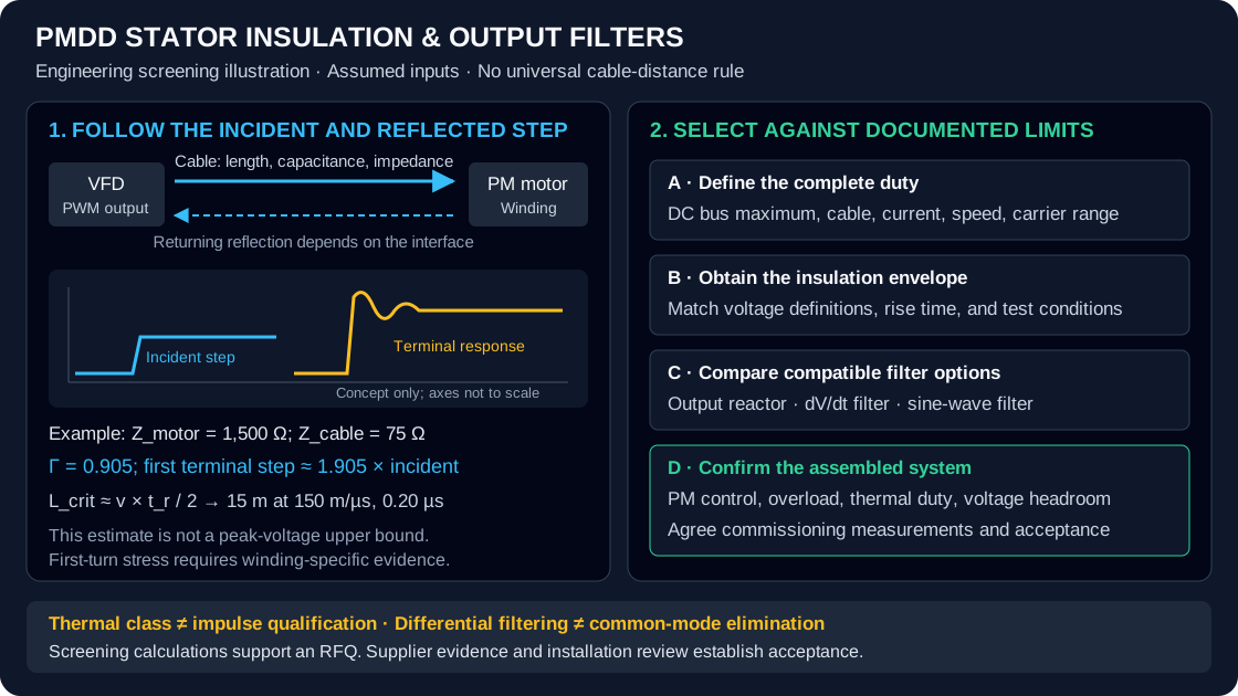
PMDD Stator Insulation & dV/dt Filter Sizing: Cable Reflection, PDIV Limits, and Output Filter Selection
Compare PMDD stator insulation and dV/dt filter sizing: cable reflection, PDIV evidence, and drive limits. Prepare an RFQ for a supplier compatibility review.
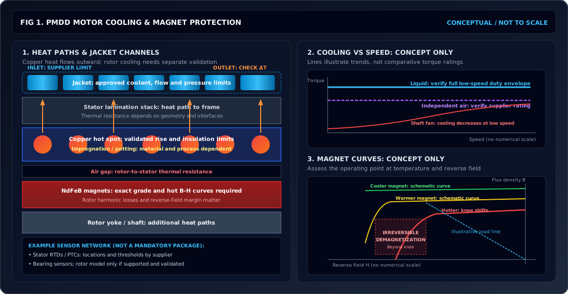
PMDD Motor Thermal Management & Cooling Sizing: Liquid Water Jacket, Forced-Air Convection, and NdFeB Magnet Thermal Limits
Size PMDD motor cooling with a worked flow example. Compare water jackets and forced air, check NdFeB thermal limits, and prepare your cooling RFQ for review.
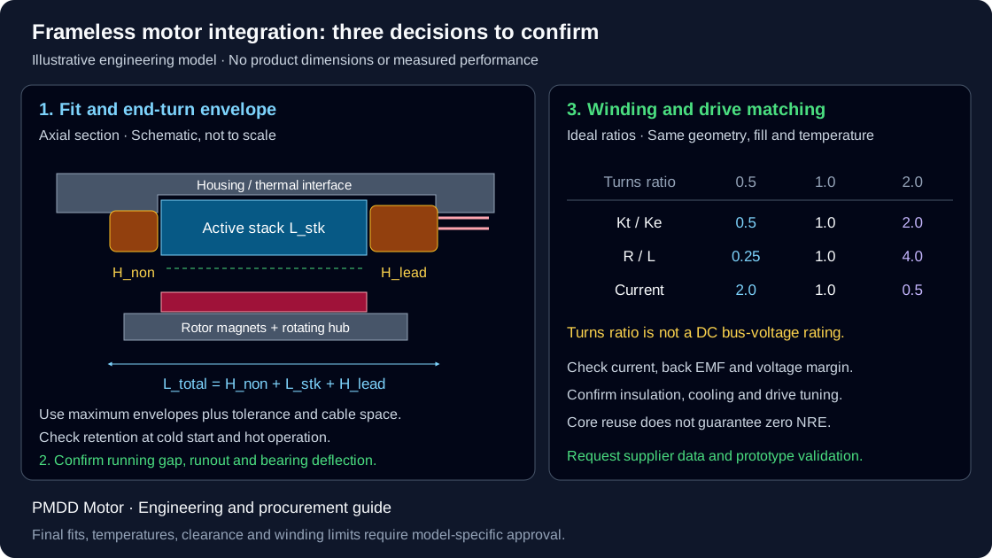
Frameless Torque Motor Integration: Housing Bore Fits, End-Turn Stack, and Winding Adaptation
Plan frameless torque motor integration with housing-fit calculations, end-turn clearance checks, winding trade-offs, and RFQ checklist. Request a CAD review.