
PMDD Motor Thermal Management & Cooling Sizing: Liquid Water Jacket, Forced-Air Convection, and NdFeB Magnet Thermal Limits
Size PMDD motor cooling with a worked flow example. Compare water jackets and forced air, check NdFeB thermal limits, and prepare your cooling RFQ for review.
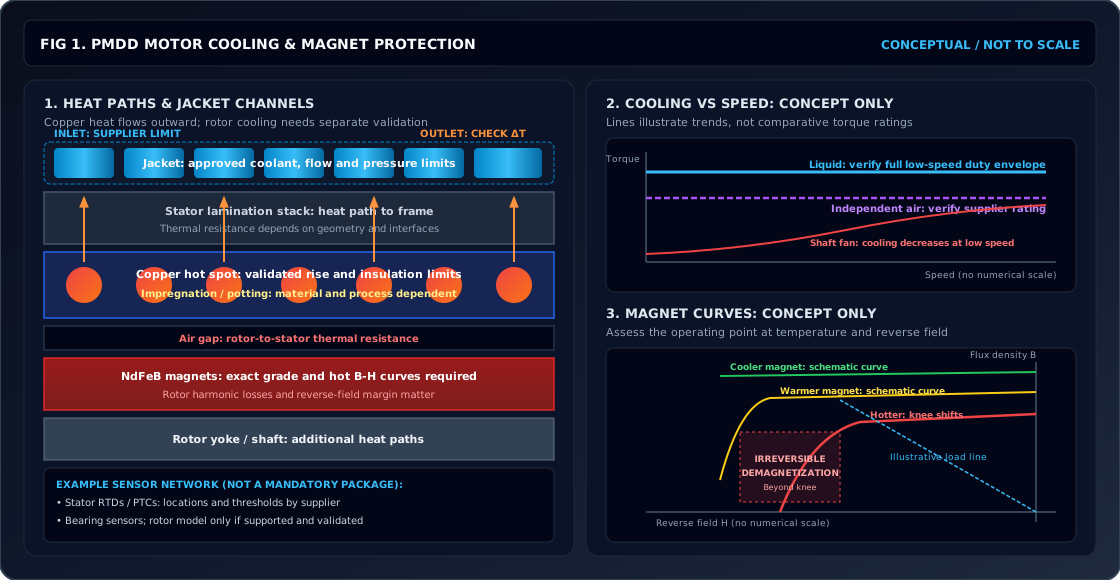
Quick answer: Size PMDD motor cooling from losses at the required continuous torque and speed, then check winding and rotor temperatures separately. Independent blowers (IC416) suit sites without cooling-water utilities; liquid jackets (commonly specified as IC71W) can help meet a compact envelope. A shaft-mounted fan (IC411) needs a verified low-speed torque rating. Cooling designation alone establishes neither ingress protection nor a safe NdFeB magnet temperature.
Published: November 2, 2026 · Last reviewed: November 2, 2026 · Global engineering and procurement guidance · Publisher: PMDD Motor. This guide supports preliminary cooling selection and RFQ preparation for industrial gearless permanent-magnet drives. The worked calculation is an illustrative steady-state energy balance, not a motor test or a guaranteed catalog rating. It does not establish transient overload capability, hazardous-area approval, marine certification, or fault protection settings. Confirm loss maps, coolant properties, pressure limits, and magnet operating curves with the motor and drive suppliers before procurement.
Evaluating a high-torque direct-drive retrofit or sizing a liquid-cooled motor frame? Submit your machine duty cycle, available cooling media, and mechanical envelope for an engineering thermal review.
The header diagram illustrates heat paths, cooling arrangements, and magnet operating curves. Open the full-size thermal architecture schematic. Geometry and curves are conceptual; they are not dimensioned jacket drawings or measured performance data.
PMDD Continuous Torque, Liquid Jacket Hydraulics & Magnet Protection Limits
- Q_loss = m_dot * C_p * Delta_T = rho * V_dot * C_p * (T_out - T_in) [Coolant Thermal Balance]
- Re = (rho * v * D_h) / mu [Use per-channel flow and coolant viscosity]
- Delta_P = f * (L / D_h) * (rho * v^2 / 2) + Sigma(K * rho * v^2 / 2) [Hydraulic Pressure Drop]
- B_r(T) = B_r(20°C) * [1 + alpha_Br * (T - 20)] [Reversible Flux Loss]
- Magnet approval: supplier B-H curves at maximum rotor temperature and reverse field
- Shaft-fan flow decreases with speed; require the supplier's continuous torque-speed envelope for the actual cooling arrangement.
- Liquid cooling can reduce frame size, but no universal torque-density or mass advantage applies across different designs.
- A cool winding RTD does not prove a cool rotor. Request a validated rotor thermal model or test evidence at the worst operating point.
- Continuous thermal loss dissipation requirement (kW) under rated torque and speed.
- Available cooling medium: deionized water, industrial closed-loop water, or water-glycol mix (specify % concentration).
- Coolant supply inlet temperature (T_in) and available flow range (L/min), confirmed at site conditions.
- Maximum permissible hydraulic pressure drop across the motor jacket (Delta_P in bar or kPa).
- Ambient air temperature (T_amb), altitude, environmental ingress class (IP55, IP65, IP67), and hazardous area certification.
1. The Low-Speed High-Torque Thermal Dilemma: Why Shaft-Mounted Fans Fail
In many geared drivetrains, the motor runs fast enough for a shaft-mounted fan to move useful air over the frame. At direct-drive process speeds, the same fan cannot be assumed to provide the same cooling. Class F (155°C) and Class H (180°C) describe insulation thermal classes, not automatic alarm settings or permission to run every component at those temperatures.
When machinery builders eliminate the gearbox and transition to a 1:1 Permanent Magnet Direct Drive (PMDD) configuration, the motor shaft speed matches the process operational speed directly—often between 20 RPM and 250 RPM. This operational shift fundamentally alters the physics of heat rejection:
-
Aero-Mechanical Airflow Collapse: Volumetric flow rate (
V_dot) generated by a centrifugal or axial shaft fan scales linearly with rotational speed (n), while static pressure (ΔP) scales with the square of speed (n²), and fan shaft power consumption scales with speed cubed (n³):Fan airflow ∝ n; fan pressure ∝ n²Under fan-law similarity assumptions, 75 RPM versus 1,500 RPM gives 5% of the airflow and 0.25% of the pressure. Actual flow follows the fan and system curves; these ratios do not establish a motor torque derating.
-
Torque-Proportional Current & Joule Heating: Continuous electromagnetic torque in a permanent magnet synchronous motor is governed by the vector cross-product of stator current and rotor flux:
T_e = (3/2) × p × [Ψ_pm × I_q + (L_d − L_q) × I_d × I_q]Here
pis the pole-pair count,Ψ_pmis PM flux linkage, andI_d/I_quse the peak-current d–q convention; do not substitute RMS phase current directly. At a given torque, phase current and copper heating can remain high even when mechanical output power falls with speed. Copper dissipation isP_cu = 3 × I_rms² × R_ac(T), with current and resistance expressed consistently per phase. At standstill, do not estimate losses from rated-speed efficiency. -
The Air-Gap Thermal Barrier: A synchronous PM rotor has no induction-cage slip loss from the fundamental field. However, the mechanical air gap separating the stator bore from the rotating permanent magnets possesses a very low thermal conductivity (
k_air ≈ 0.026 W/(m·K)). The air gap serves as a severe thermal insulator. Heat generated in the stator cannot easily travel across the gap, while heat generated within the rotor (from high-frequency inverter PWM carrier harmonics and stator slot-opening permeance oscillations) cannot readily escape outward to the frame.
Consequently, a low-speed continuous-torque requirement needs a supplier-verified thermal rating. Independent air or liquid cooling often helps, but a universal percentage derating cannot be inferred from speed alone.
2. PMDD Cooling Topologies Compared: IC410, IC416, and IC71W
Match cooling to duty cycle, site utilities, and environment. IEC 60034-6 classifies cooling circuits and coolant movement; it does not assign torque density, IP ratings, or pump pressures. Confirm the full IC designation on the supplier drawing, particularly for jacket and heat-exchanger variants.
| Arrangement | Heat path | Useful when | Required utility | Maintenance concern | Evidence to request |
|---|---|---|---|---|---|
| IC410: non-ventilated frame | Natural convection and radiation | Passive cooling can meet the duty | Free air and mounting heat path | Dust, frame clearance, bearings | Continuous/intermittent torque rating at site ambient |
| IC416: independent blower | Forced air over the housing | Plant cooling water is unavailable | Blower power and unobstructed airflow | Filters, fouling, blower failure | Airflow requirement and low-speed heat-run result |
| Liquid jacket, commonly IC71W | Stator-to-frame-to-liquid conduction | Envelope or room heat rejection is constrained | Approved coolant, pump, heat exchanger | Leakage, corrosion, fouling | Flow–pressure curve, inlet limit, maximum working pressure |
| IC616: air-to-air exchanger | Internal air loop to external air | A closed internal air circuit is needed | Auxiliary fan power and external airflow | Exchanger cleaning, fan service | Rating at specified ambient and dirty-filter condition |
| IC81W: air-to-water exchanger | Internal air loop to water exchanger | A large enclosed machine has water utilities | Water circuit and internal circulation | Exchanger fouling, condensation | Water quality limits and separate air/water performance |
| Direct oil cooling: design-specific | Oil contacts selected active parts | An integrated design supports direct cooling | Compatible fluid, filtration, pump | Fluid ageing, seals, material compatibility | Validated electrical, hydraulic, and thermal design; no IC code inferred here |
Engineering Trade-Off Analysis: Forced Air (IC416) vs Liquid Jacket (IC71W)
For mainstream industrial direct-drive installations, the choice almost always narrows to IC416 (Forced Air) versus IC71W (Liquid Water Jacket).
When to Choose Forced Air (IC416):
- Utility Constraints: The installation site (such as an overland belt conveyor or remote aggregate quarry) lacks treated cooling water loops or space for chiller piping.
- Capital Expenditure Sensitivity: Compare installed blower costs with the complete liquid loop, including pump, exchanger, controls, piping, and maintenance. Savings require project quotations.
- Freezing Hazards: Unheated outdoor facilities subject to sub-zero winters where plant operators cannot guarantee uninterrupted glycol conditioning.
- Motor Sizing Margin: The physical machine frame has ample spatial volume to accommodate a larger motor outer diameter (OD) and longer stack length.
When to Choose Liquid Cooling (IC71W):
- Compact Envelope & Torque Density: Compare candidate frames at the same torque, speed, duty, and coolant inlet temperature. Liquid cooling may reduce active volume; the external skid still needs space.
- Harsh & Corrosive Environments: A sealed housing can reduce exposure of internal parts. Specify IP protection and corrosion resistance separately; an IC code does not establish either.
- Acoustic Compliance: Removing a motor blower can reduce local fan noise, but include pump and heat-exchanger noise in the installed-system assessment.
- Thermal Heat Rejection to Ambience: A liquid loop can move heat outside the production room only when its final exchanger rejects heat elsewhere. Request the fraction of motor loss entering the liquid rather than assuming full capture.
3. Liquid Cooling Jacket Hydraulics & Thermodynamic Sizing
A liquid cooling jacket consists of an annular cavity formed between the motor stator housing and an outer sleeve. Fluid channels are typically arranged in a single continuous helical spiral around the stator back-iron or a multi-pass axial serpentine manifold.
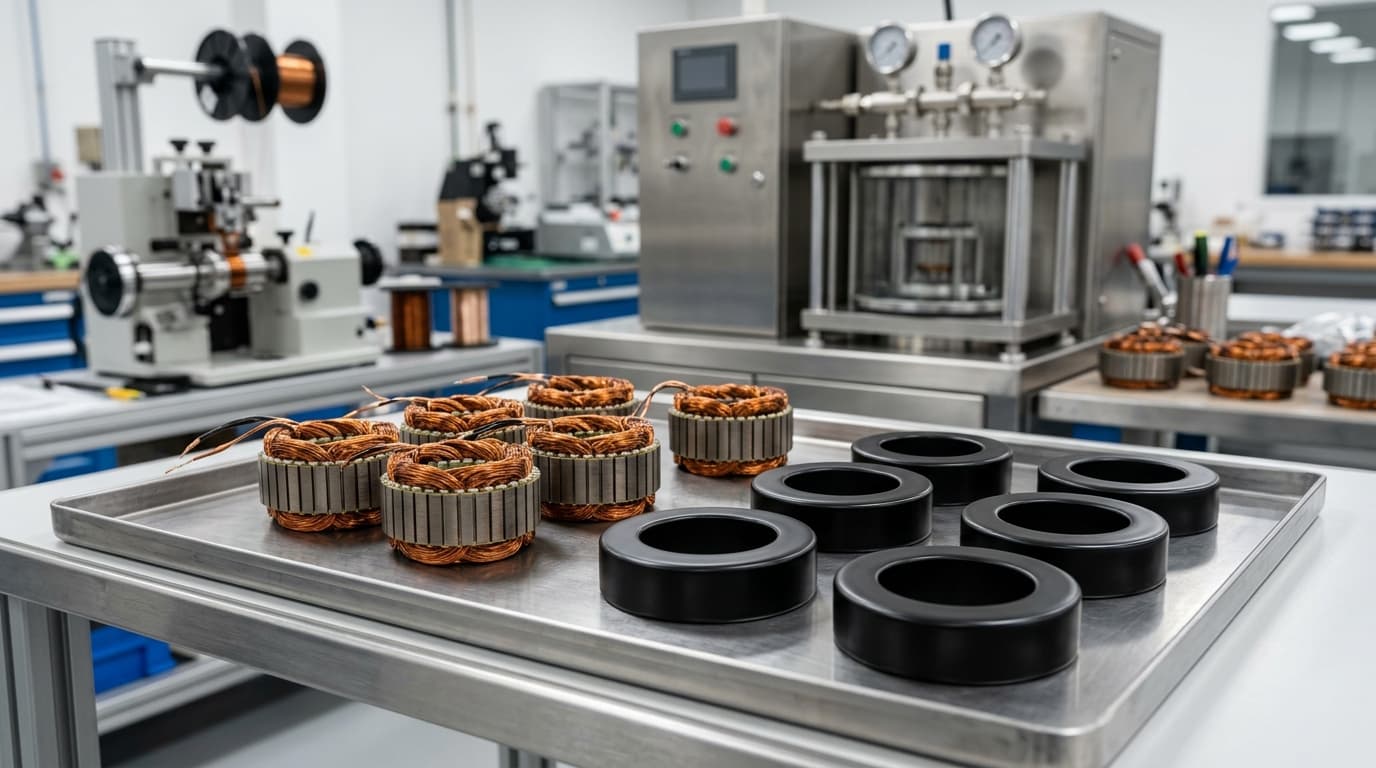 Figure 2: Illustrative winding and impregnation reference, not a verified production cross-section or test result. Reducing air voids can improve the winding-to-core heat path; the benefit depends on materials and manufacturing quality.
Heat Removal and Coolant Flow Rate Equation
The thermal energy removed by the coolant circuit must equal the total internal electrical and magnetic losses rejected to the jacket:
Q_loss = m_dot × C_p × (T_out − T_in) = ρ × V_dot × C_p × ΔTWhere:
Q_loss= Heat entering the jacket in watts. Total motor loss includes copper, core, rotor, and mechanical losses. Use the measured or modeled heat split; if unknown, screen the loop against the full motor loss rather than deducting an assumed radiation percentage.m_dot= Coolant mass flow rate (kg/s).V_dot= Volumetric flow rate in cubic metres per second in the equation; multiply by 60,000 to obtain litres per minute.ρ= Fluid density in kg/m³ at the operating temperature.C_p= Specific heat in J/(kg·K). Obtain both properties from the coolant supplier for the actual concentration, specifying mass or volume basis.ΔT = T_out − T_in= Coolant temperature rise. Select it together with allowable winding temperature, inlet temperature, and jacket heat-transfer performance; it is not a universal motor standard.
Sizing Example:
A hypothetical motor delivers 45 kW shaft output at 120 RPM, with an assumed 92.5% efficiency at that operating point. This corresponds to approximately 3,581 N·m. For this arithmetic example only, assume a 50/50-by-volume water–ethylene-glycol blend, density 1,065 kg/m³, specific heat 3,350 J/(kg·K), and allowable coolant rise 6 K. These are assumed calculation inputs, not a coolant specification.
- Total losses:
P_loss = 45,000 × (1 − 0.925) / 0.925 ≈ 3,649 W ≈ 3.65 kW. - Assuming 90% of losses enter the liquid jacket (
Q_loss ≈ 3,284 W), using a 50/50 water-glycol coolant with an allowableΔT = 6 K:
V_dot = 3,284 / (1,065 × 3,350 × 6) ≈ 0.0001534 m³/s ≈ 9.2 L/minThe energy balance gives 9.2 L/min for the assumed 90% jacket heat share. If the heat split is unknown, using all 3.65 kW gives 10.2 L/min. Neither figure proves sufficient local heat transfer or selects a pump: verify the per-channel flow distribution, supplier pressure-drop curve, maximum inlet temperature, and winding/rotor heat-run results. Increasing flow cannot indefinitely compensate for hotter inlet coolant.
Checking Channel Flow Regime (Reynolds Number Criteria)
Bulk heat capacity alone does not establish the channel-wall heat-transfer coefficient. Evaluate the flow regime in each parallel branch, not only at the motor supply port.
For a conventional internal duct, Re < 2,300 and Re > 4,000 are preliminary laminar and turbulent screening ranges. Helical channels, entry effects, roughness, and manifolds require geometry-specific validation; laminar cooling can still be adequate in a validated design.
Re = ρ × v × D_h / μ = 4 × ρ × V_dot / (μ × P_wet)Where:
v= Mean velocity in the individual channel, in m/s. There is no universal velocity limit independent of geometry, fluid, and material.D_h= Hydraulic diameter of the rectangular duct (D_h = 4A / P_wet = 2wh / (w + h)), whereAis flow area,P_wetis wetted perimeter, andw/hare channel width/depth in metres.μ= Dynamic fluid viscosity (Pa·s).
[!WARNING] The Low-Temperature Glycol Viscosity Penalty: Glycol concentration and temperature affect viscosity, heat capacity, pump delivery, and Reynolds number. Use the selected fluid's cold-start and operating-temperature property curves. Check the pump–system operating point and minimum-flow interlock; a water-only pump selection may be unsuitable for the blend. Cold startup does not by itself imply an immediate thermal trip.
Hydraulic Pressure Drop and Jacket Construction
Pressure drop across the motor jacket consists of wall friction plus geometric turning losses across 180-degree bends:
ΔP = [f × (L / D_h) + ΣK] × ρ × v² / 2Use a Darcy friction factor in this equation, with channel length, hydraulic diameter, roughness, and bend-loss coefficients. Add hoses, valves, filters, and the heat exchanger to obtain the system curve. Select the pump where that curve intersects its delivery curve at the actual fluid viscosity. Jacket pressure drop and maximum working pressure are separate specifications: confirm both, including static fill pressure and pump shutoff pressure, against the supplier rating.
4. Rotor NdFeB Magnet Thermal Limits & Demagnetization Protection
Winding insulation class does not establish magnet, adhesive, bearing, or sensor temperature capability. The allowable motor operating envelope is constrained by whichever component reaches its validated limit first. Class H insulation does not imply a generic 200°C short-term overload allowance.
Sintered NdFeB properties vary with grade, shape, and temperature. Remanence affects back-EMF and torque constant; intrinsic coercivity describes resistance to demagnetization. For example, Arnold lists N38SH coefficients of −0.12%/°C for remanence and −0.535%/°C for intrinsic coercivity. Apply coefficients only within the supplier's stated range; do not extrapolate them into a universal safe-temperature calculation. Source: Arnold NdFeB grade table.
The Knee-Point Danger Zone & Irreversible Demagnetization
The normal B-H demagnetization curve of an NdFeB magnet is linear in the second quadrant at room temperature. As temperature rises, the curve develops a sharp downward bend known as the knee point.
Reversible flux reduction can recover on cooling if the operating excursion avoids irreversible loss. Compare the local magnet operating point with the supplier's temperature-dependent demagnetization curves, including the worst reverse field from:
- High negative
d-axis current (I_d) applied during aggressive high-speed field-weakening; - A sudden three-phase symmetrical terminal short circuit; or
- A drive or winding fault producing a demagnetizing current.
An excursion beyond the knee can cause irreversible demagnetization and reduce torque per ampere. Symptoms alone cannot diagnose it; compare back-EMF or flux measurements at matched speed and temperature with the baseline and investigate other drive or winding faults.
Selecting NdFeB Thermal Grades for PMDD Machines
Selected Arnold catalog values are shown below. They describe individual grades, not universal suffix guarantees or approved motor operating temperatures. Grade-specific curves and the assembled motor's load line still govern selection.
| Example grade | Catalog maximum use temperature (°C) | Minimum Hcj at room temperature (kA/m) |
|---|---|---|
| N38 | 80 | 955 |
| N38M | 100 | 1,114 |
| N38H | 120 | 1,353 |
| N38SH | 150 | 1,592 |
| N38UH | 180 | 1,990 |
| N35EH | 200 | 2,388 |
There is no universal minimum SH or UH grade for all PMDD motors. Request the selected grade's temperature-dependent curves and a demagnetization assessment at peak current, field weakening, and credible faults. A higher catalog temperature does not by itself demonstrate a safe motor design.
5. Thermal Sensor Architecture & Drive Protection Strategies
At standstill, the current vector can hold a fixed position relative to the windings and produce uneven phase heating. Current distribution depends on rotor angle and drive control. The following is an illustrative sensor arrangement, not a mandatory package; sensor placement, redundancy, and thresholds require supplier agreement.
+-----------------------------------------------------------------------------------+
|               DISTRIBUTED PMDD THERMAL MONITORING TOPOLOGY                       |
+-----------------------------------------------------------------------------------+
|                                                                                   |
|  [ STATOR CORE SLOTS ]                                                            |
|  ├── Phase U Hotspot: 2× PT100 RTD (Slot Middle & Tooth Tip) ──────┐              |
|  ├── Phase V Hotspot: 2× PT100 RTD (Slot Middle & Tooth Tip) ──────┼──> PLC / VFD  |
|  └── Phase W Hotspot: 2× PT100 RTD (Slot Middle & Tooth Tip) ──────┤   Analog In  |
|                                                                    │   (3-Wire)   |
|  [ WINDING END-TURNS ]                                             │              |
|  └── PTC Thermistor Chain (Supplier-Selected Threshold) ──────────┼──> Thermal   |
|                                                                    │    Relay / VFD|
|  [ BEARING HOUSINGS ]                                              │              |
|  ├── Drive-End (DE) Bearing: 1× PT100 RTD (Inner Ring Seat) ───────┤              |
|  └── Non-Drive-End (NDE) Bearing: 1× PT100 RTD ───────────────────┤              |
|                                                                    │              |
|  [ COOLING JACKET PORTS (IC71W) ]                                  │              |
|  ├── Coolant Supply Inlet PT100 + Digital Flow Switch ─────────────┤              |
|  └── Outlet PT100 + Inlet/Outlet Pressure Taps for ΔP ─────────────┘              |
+-----------------------------------------------------------------------------------+
1. Dual Stator RTD Redundancy
An example redundancy scheme uses two 3-wire PT100 sensors per phase. The manufacturer must select locations that represent likely hot spots without compromising insulation. Define warning, derating, trip, sensor open/short detection, and reset behavior using the validated hot-spot offset and thermal time constants. Insulation class alone does not determine these settings.
2. End-Turn PTC Thermal Protection
A PTC chain connected to a compatible relay or drive input can provide independent thermal protection. Neither PTCs nor RTDs replace electronic overcurrent, short-circuit, or ground-fault protection. Specify the PTC response and interface with the manufacturer. A thermal trip is not automatically a safety-rated STO function; any STO or controlled-stop requirement belongs in the machine risk assessment and drive safety design.
3. Rotor Magnet Temperature Estimation (LPTN Algorithms)
Some matched motor–drive systems support a Lumped-Parameter Thermal Network (LPTN) observer; many general-purpose drives do not estimate magnet temperature. A suitable calibrated model may use:
- Measured stator winding RTD temperature;
- Real-time phase current magnitude (
I_q, I_d); - Inverter PWM switching frequency (
f_sw) harmonic losses; - Rotational speed (
n); and - Thermal parameters calibrated and validated by the motor supplier.
Confirm that the delivered drive implements the agreed model, its error margin, and the response to missing sensors. Use the approved rotor limit and reverse-current envelope to configure derating or shutdown. Neither an SH suffix nor a winding RTD reading establishes a universal 115°C rotor trip setting.
6. PMDD Thermal Specification & RFQ Checklist
When preparing a Request for Quotation (RFQ) for high-torque PMDD motors, procurement teams should require motor manufacturers to supply explicit thermal performance figures rather than vague marketing claims.
Use this operational checklist to evaluate vendor proposals:
Primary Procurement & Thermal Sizing Checklist
- Continuous Torque at Nominal Speed: Verified under steady-state thermal equilibrium (
S1continuous duty) at specified coolant flow and inlet temperature. - Cooling Mode Designation: Confirmed per IEC 60034-6 (e.g., IC416 with auxiliary blower voltage/phase specified, or IC71W with port pipe thread size).
- Coolant Compatibility & Metallurgy: Jacket, seal, hose, inhibitor, and mixed-metal compatibility documented, including water chemistry and concentration basis.
- Jacket Hydraulics: Flow–pressure curve at hot and cold fluid conditions, minimum flow, maximum inlet temperature, maximum working pressure, and pump shutoff pressure agreed.
- Winding Insulation & Impregnation: Thermal class, temperature-rise limit, hot-spot allowance, and impregnation method identified for the specified duty.
- Permanent Magnet Alloy & Grade: Exact grade, temperature-dependent demagnetization curves, and reverse-field assessment supplied; no generic suffix-only approval.
- Temperature Sensor & Protection Package: Locations, wiring, redundancy, thresholds, flow/blower interlocks, and drive actions documented, with separate electrical fault protection.
- Factory Heat Run Test Evidence: Acceptance method and applicable IEC 60034-1 requirements agreed; record torque, speed, current, coolant/ambient conditions, winding temperatures, and stabilization criterion. Loss/efficiency testing is a separate scope.
Need help turning missing supplier data into an inquiry? Send the checklist and your available cooling utilities for scope review.
RFQ Data Input Matrix for Mechanical & Cooling Designers
Before signing off on motor procurement, ensure the following parameters are mutually documented between your engineering team and the motor supplier:
+-----------------------------------+-----------------------------------+
| Parameter Description             | Value / Unit                      |
+-----------------------------------+-----------------------------------+
| Required Continuous Shaft Torque  | [________] Nm                     |
| Base Operational Shaft Speed      | [________] RPM                    |
| Max Overload Torque / Duration    | [________] Nm for [____] seconds  |
| Duty Cycle / Load Profile         | [  ] S1  [  ] Other: attach cycle |
| Ambient Temperature Envelope      | Min: [____] °C  /  Max: [____] °C |
| Available Cooling Mode            | [  ] IC71W Liquid  [  ] IC416 Air |
| Coolant Composition / Basis       | [____]% Glycol  [mass / volume]   |
| Max Permissible Coolant Inlet Temp| [________] °C                     |
| Plant Water Supply Pressure / Head| [________] bar                    |
| Enclosure Ingress Protection (IP) | [  ] IP55   [  ] IP65   [  ] IP67 |
| Area Classification               | [  ] Safe Area   [  ] ATEX Zone 2 |
+-----------------------------------+-----------------------------------+
7. Frequently Asked Questions (FAQ)
Can I use untreated tap water in a PMDD liquid cooling jacket?
Use water only if it meets the motor and coolant suppliers' chemistry limits. Hardness, chlorides, conductivity, pH, dissolved oxygen, and mixed metals affect scale and corrosion. Untreated tap water may be unsuitable; deionized water alone is not automatically a compatible coolant either. Obtain an approved water/inhibitor specification and maintenance interval for the actual jacket, seals, and loop materials.
What happens to motor continuous torque if the cooling blower fails on an IC416 motor?
The rated forced-air cooling condition is lost. Residual passive cooling does not create a newly certified IC410 rating or a known safe run-on time. Specify airflow or blower-status monitoring and the supplier-approved derating or stop response. Consider load inertia and process hazards when choosing that response; do not assume immediate torque removal is safe for every machine.
Is rotor magnet demagnetization always worse at low speed?
No. Low-speed high-torque operation can sustain high copper losses and weak internal circulation, while high-speed operation can increase rotor harmonic losses and require negative d-axis field-weakening current. Assess rotor temperature and the local reverse field across the full torque-speed envelope, including stalls and credible faults. Speed alone does not rank demagnetization risk.
Can we retrofit a liquid-cooled PMDD motor into an application that previously had an air-cooled motor?
Potentially. Check the shaft and mounting interface, continuous and peak torque, drive/feedback compatibility, piping access, and coolant availability. Size the pump and exchanger from actual losses and the complete loop pressure-drop curve. Include leak detection and condensation control where needed. Frame-size or mass savings require comparison of the specific quoted motors at matching duty conditions.
How does adding glycol to cooling water affect motor continuous torque ratings?
Glycol generally reduces heat capacity and increases viscosity relative to water, changing both heat transfer and pump delivery. Recalculate with properties for the selected blend and temperature, then check the motor supplier's coolant-specific rating. There is no universal torque derating or compensating flow increase. State the glycol type, inhibitor package, concentration basis, freeze requirement, and cold-start temperature in the RFQ.
8. Authoritative References & Standards
-
IEC 60034-6:1991 — Methods of cooling (IC Code). Official catalog scope for circuit arrangements and coolant movement designations; not a source of generic torque-density or IP ratings.
-
IEC 60034-1:2022 — Rating and performance, official preview. Establishes the rotating-machine scope and associated standards. The preview is not the complete acceptance procedure; agree the applicable edition, amendments, and test method with the supplier.
-
Arnold Magnetic Technologies — NdFeB grades and magnetic properties. Primary manufacturer data for the six selected grades and the N38SH temperature coefficients above; catalog values do not approve an assembled motor's reverse-field margin.
The flow calculation is independently reproducible from the stated assumptions. This guide presents no first-party heat-run measurements or customer performance claims.
9. Engineering Review & Application Inquiries
Sizing thermal management systems for gearless permanent magnet drives requires balancing continuous torque targets, coolant hydraulics, environmental sealing, and rotor magnet safety margins. Undersizing a cooling loop leads to chronic thermal tripping and irreversible magnet demagnetization, while overspecifying chiller infrastructure adds unnecessary capital expense.
Use the PMDD Motor inquiry channel to share the application scope and identify the supplier evidence still needed. Confirm engineering deliverables, testing, and protection responsibilities in the quotation rather than assuming they are included.
Ready to evaluate your direct-drive cooling requirements? Submit your motor torque-speed curve, envelope limits, and site cooling utilities for an engineering thermal review.
Send a product name, model number, drawing, or application brief. We source across motors, generators, drives, and OEM components, then coordinate suitable suppliers and a project-specific offer.
Email the Sourcing Desk (RFQ & Drawings)
inquiry@pmddmotor.com
Send your operating parameters, interface drawings, or nameplate photos to confirm product fit, documentation scope, and quotation terms per project.
WhatsApp the Sourcing Desk
Share nameplate photos, reference part numbers (Kollmorgen / TQ / Celera), or OD/ID limits so we can coordinate a supplier quotation.
Engineering Author

Project inquiry guidance. Articles explain general methods and do not report tests on PMDD Motor or supplier products.
Engineering Categories
Prepare the operating and interface information for an application review. Requested drawings, test records, and supplier evidence are confirmed per project.
Related Engineering Guides
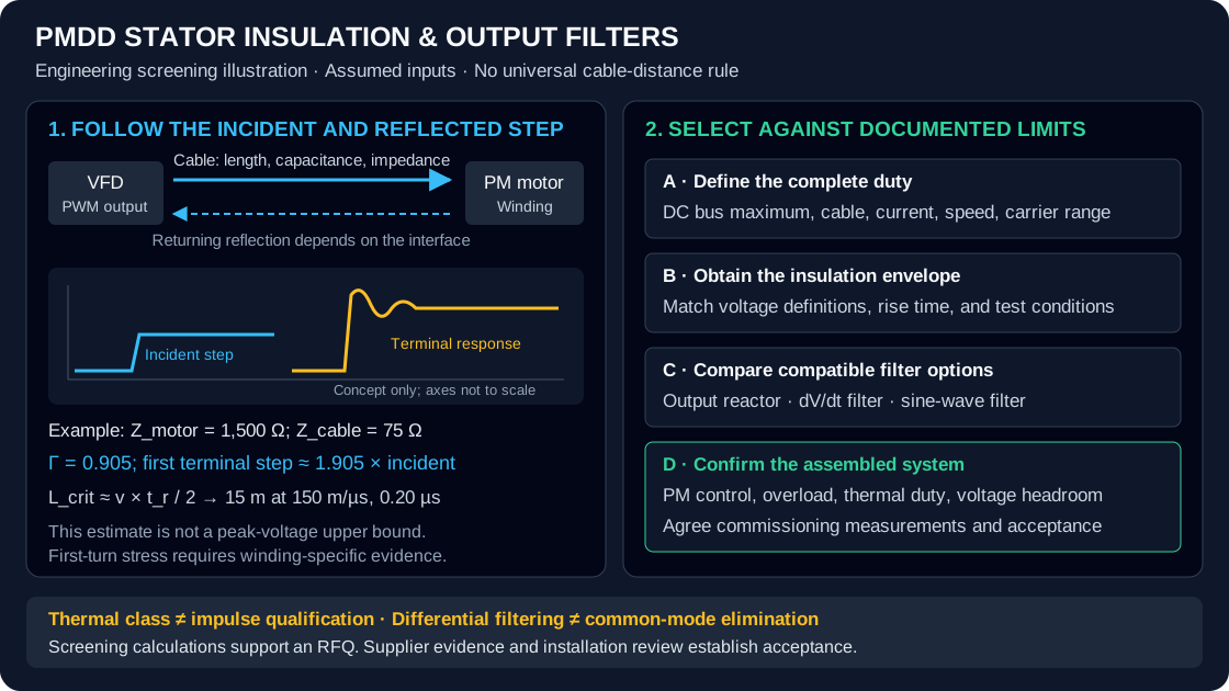
PMDD Stator Insulation & dV/dt Filter Sizing: Cable Reflection, PDIV Limits, and Output Filter Selection
Compare PMDD stator insulation and dV/dt filter sizing: cable reflection, PDIV evidence, and drive limits. Prepare an RFQ for a supplier compatibility review.
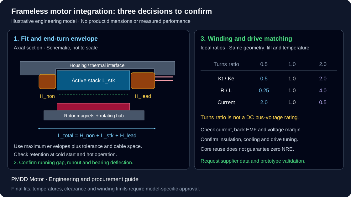
Frameless Torque Motor Integration: Housing Bore Fits, End-Turn Stack, and Winding Adaptation
Plan frameless torque motor integration with housing-fit calculations, end-turn clearance checks, winding trade-offs, and RFQ checklist. Request a CAD review.
PMDD Bearing Sizing & EDM Protection: Thrust Loads, L10h Life, and VFD Shaft Currents
Size PMDD motor bearings for thrust and L10h life, compare VFD shaft-current protection, and prepare an RFQ with load, lubrication, and commissioning requirements.