
Frameless Torque Motor Integration: Housing Bore Fits, End-Turn Stack, and Winding Adaptation
Plan frameless torque motor integration with housing-fit calculations, end-turn clearance checks, winding trade-offs, and RFQ checklist. Request a CAD review.
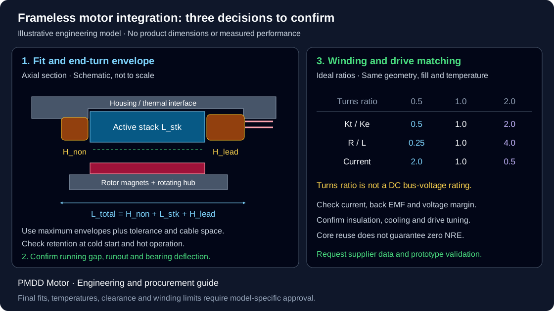
Quick answer: Frameless torque motor integration requires three linked decisions: choose a stator-to-housing fit that retains torque across the operating temperature range; reserve the supplier's maximum end-turn and lead-exit envelopes on both ends; and select a winding against the drive's voltage, current, and speed limits. A tolerance code or bus-voltage label alone cannot establish compatibility.
Published and reviewed: October 29, 2026 · Global engineering and procurement guidance · Publisher: PMDD Motor. This guide applies to frameless direct-drive brushless permanent-magnet (BLDC / PMSM) kits for robotic joints, rotary stages, and gimbals. The worked calculations are illustrative design checks, not measurements of PMDD Motor or supplier products. They do not establish medical-device suitability or regulatory compliance. Final fits, thermal limits, insulation requirements, and acceptance criteria need model-specific supplier approval.
Frameless motors let the machine structure serve as the motor frame and heat sink; the assembly still requires bearings, retention, and feedback. Direct drive removes gearbox backlash, while bearing compliance, encoder errors, and structural deflection still affect positioning.
Designing a custom robotic joint or evaluating an alternative kit? Send your envelope CAD and target torque-speed requirements for a supplier coordination review.
The header diagram is an illustrative cross-section and winding-ratio example. Open the full-size integration diagram to review the variables; it is not a dimensioned manufacturing drawing.
Mechanical Housing Tolerancing, CAD Stack & Winding Adaptation Rules
- Km = Torque / sqrt(P_copper) [Use consistent current conventions]
- kw = N2 / N1; Kt ~ kw; R_ll ~ kw^2 [Ideal same-fill model]
- Delta_D_th = D0 * (alpha_Al - alpha_Fe) * Delta_T [Bore Differential]
- L_total = H_lead + L_stk + H_non_lead [Asymmetric Stack]
- Avoid unapproved cold pressing of laminated stators; select bonding, shrink fitting, or clamping against the model-specific installation instructions.
- End turns and lead exits may be asymmetric; use maximum supplier envelopes plus tolerances and cable bend space.
- Winding changes can reuse the magnetic core, but insulation, current, tooling costs, and validation remain subject to supplier confirmation.
- Stator OD tolerance class and housing bore material (e.g., 6061-T6 vs 7075-T6 vs steel).
- Operating temperature envelope (T_ambient, min cold startup, max continuous winding temp).
- Continuous stall torque (Nm), peak acceleration torque, and continuous base speed (RPM).
- Available DC bus voltage (VDC) and servo drive continuous/peak current limits (Arms).
- Rotor thru-bore ID, hollow shaft clamping method, and encoder feedback protocol.
1. Mechanical Housing Architecture: Thermal Expansion Mismatch & Bore Tolerancing
When integrating a frameless stator into an aluminum actuator housing, mechanical engineers encounter a fundamental physics conflict: the thermal expansion mismatch between structural aluminum and electrical silicon steel.
Housing material (Aluminum 6061-T6 / 7075-T6):  alpha_Al ≈ 23 × 10^-6 / K
Stator core material (Laminated Silicon Steel): alpha_Fe ≈ 11 × 10^-6 / K
Differential thermal expansion rate:            Delta_alpha ≈ 12 × 10^-6 / K
As the motor operates under continuous load, copper I²R losses and stator iron losses elevate the joint temperature. If a joint heats from an ambient assembly temperature of 20°C to a continuous operating temperature of 80°C (ΔT = 60 K), the aluminum housing bore expands more than twice as fast as the laminated stator core.
Delta_D_th = D_0 * (alpha_Al - alpha_Fe) * Delta_TFor a typical 100 mm outside diameter (D_0) stator:
Delta_D_th = 100 mm * (12 * 10^-6 / K) * 60 K = 0.072 mm (72 micrometers)The differential growth is 72 micrometers, not the resulting free clearance. For a hypothetical 100.000 mm bore and 100.015 mm stator at 20°C, the initial diametrical interference is 0.015 mm. Assuming both parts reach 80°C uniformly and using the illustrative coefficients above:
Housing bore at 80°C = 100.000 * (1 + 23e-6 * 60) = 100.138 mm
Stator OD at 80°C    = 100.015 * (1 + 11e-6 * 60) = 100.081 mm
Free diametral gap   = 100.138 - 100.081 = 0.057 mm
This unconstrained expansion model predicts loss of interference. It ignores joint stress, temperature gradients, adhesive behavior, and housing flexibility. If the stator and housing run at different temperatures, calculate their growth separately. A real fit calculation must use minimum and maximum diameters at cold start, assembly, and hot operation. H7/js6 is a hole/shaft tolerance pairing, not a fixed micrometer allowance for every diameter; ISO 286-1 explains the fit system.
Loss of retention can let the core move under reaction torque, disturb the air gap, damage leads, or increase thermal resistance. These are risks to evaluate, not inevitable outcomes for every aluminum housing.
1.1 Why Unapproved Cold Pressing Can Damage Laminations
An interference fit can impose axial shear and radial distortion on a laminated stator. Do not transfer a solid-steel bushing press procedure to an unprotected lamination stack. Burrs, damaged insulation, or a distorted bore can compromise the assembly. The Kollmorgen mounting guidelines, printed pages 35–36, distinguish adhesive bonding, shrink fitting, and axial clamping rather than prescribing one fit for all motors.
1.2 Fit and Bonding Review Before Assembly
- Define the interface: Obtain the stator OD limits, housing alloy, wall thickness, finish, roundness, and datum requirements from the approved drawings.
- Select retention: Compare hot and cold interference, adhesive bondline limits, reaction torque, shock, and service access. A close-fitting retaining compound and a thicker structural epoxy require different gaps.
- Define seating: Locate on the approved core or mounting face. Keep the shoulder and clamps clear of windings and leads.
- Approve the process: Determine housing heating, insertion time, surface preparation, adhesive application, cure, and inspection limits with the motor and adhesive suppliers. An illustrative 100 mm aluminum bore heated from 20°C to 110°C grows about 0.207 mm; that calculation is not permission to heat a complete motor to 110°C.
- Inspect the result: Check seating, bore distortion, runout, winding-to-housing clearance, and electrical integrity after assembly and thermal cycling.
Novanta's installation guide discusses combining a light fit with bonding. If considering LOCTITE 648, consult its technical data sheet for substrate, gap, cure, and hot-strength behavior. Published coupon strength is not an allowable joint stress for your motor.
2. End-Turn Clearance & CAD Tolerance Stack-Up
In a frameless motor kit, the copper magnet wire coils loop out of the laminated stator slots at both ends before re-entering adjacent slots. These non-torque-producing loops are known as end-turns.
A frequent source of prototype redesign in robotics and precision rotary stages is treating the stator as a symmetrical cylinder in 3D CAD. The lead-exit and non-lead ends may have different maximum envelopes; the actual asymmetry is model-specific.
+-----------------------------------------------------------------------------------+
|               ILLUSTRATIVE ASYMMETRIC AXIAL END-TURN STACK-UP                |
|                                                                                   |
|           Non-Lead Side                      Lead-Exit Side (Taller)              |
|        [Short Copper Loops]     [Active Core]   [Junctions, Sensors, Jumpers]     |
|              +-------+       +-----------------+       +---------+                |
|              | H_non |       |      L_stk      |       | H_lead  | ===> Phase Wires|
|              |  end  |       |  Silicon Steel  |       | example | ===> PT1000/NTC |
|              +-------+       +-----------------+       +---------+                |
|              | <--- Total Axial Envelope L_tot = H_non + L_stk + H_lead ---> |     |
+-----------------------------------------------------------------------------------+
2.1 The Physical Cause of End-Turn Asymmetry
- Non-Lead End-Turn (
H_non_lead): The non-lead end carries winding crossovers; its compaction, binding, and potting determine the maximum envelope. - Lead-Exit End-Turn (
H_lead): Depending on the design, the lead-exit end may house:- Three-phase primary motor lead connections (
U, V, W) with high-current solder/crimp joints. - Star-point (neutral) or Delta bus ring jumpers.
- Embedded thermal sensors (PT1000 platinum RTD, KTY84, or PTC thermistors) insulated with Nomex or Kapton sleeving.
- Heavy braided fiberglass insulation sleeves for high-voltage dielectric isolation.
- Three-phase primary motor lead connections (
These features can increase the lead-side envelope. Request maximum dimensions on both ends, including potting and lead tolerances; do not assume a universal 1.5–2.5 mm difference.
2.2 Housing CAD Clearance Rules
If a mechanical engineer designs symmetrical endbells or actuator covers matching the non-lead side's envelope, tightening the housing bolts can compress the lead-exit bundle against the housing wall. Damaged wire insulation can then cause phase-to-phase or phase-to-ground shorts.
L_total = H_non_lead + L_stk + H_leadTo prevent mechanical interference:
- Stepped Housing Pockets: Machine an asymmetric pocket inside the aluminum housing that provides extra axial depth on the lead-exit side.
- Clearance Budget: Add manufacturing tolerances, assembly error, thermal movement, vibration, and cable space to each supplier maximum envelope. Mechanical clearance alone does not establish electrical creepage or clearance compliance; use the selected insulation system and application requirements.
- Lead Exit Wire Channels: Provide radiused channels, strain relief, and abrasion protection. Follow the cable supplier's static or flexing bend radius, temperature, and motion limits.
For example, a 30 mm active stack with maximum 5 mm and 7 mm end turns occupies 42 mm before any housing clearance or cable space is added. If the lead side later grows by 2 mm, that side alone needs a revised pocket; adding space at the opposite end does not resolve the interference.
3. Magnetic Air-Gap Alignment & Unbalanced Magnetic Pull (UMP)
The radial magnetic air gap is defined by the selected kit geometry:
g_0 = (ID_stator - OD_rotor) / 2Use the supplier's gap and running-clearance limits. A smaller gap can support magnetic performance but leaves less room for runout, bearing movement, and thermal or structural deflection. Torque is not a universal inverse function of gap because magnet thickness, saturation, and winding design also matter.
3.1 Unbalanced Magnetic Pull (UMP) Physics
Eccentricity makes the gap nonuniform and can create a net radial magnetic load on the bearings. Its magnitude depends on geometry, magnetization, current, saturation, and operating point. Do not select bearings from a generic UMP force estimate; request a model-specific electromagnetic assessment if the load is material to bearing life.
3.2 Machining Datum & Concentricity Budget
- Tolerance budget: Subtract the combined radial contributions from the nominal gap: locating eccentricity, rotor runout, bearing displacement, thermal movement, and load deflection. Keep the remaining minimum clearance above the supplier's requirement. Use radial offsets consistently; TIR is twice center offset only for a simple eccentric circular feature.
- Machining datum: Machine the stator locating bore and bearing seats from a common datum, preferably in one setup where feasible. Verify the completed assembly rather than assuming the machining sequence guarantees concentricity.
- Insertion tooling: Use a guided fixture and supplier-approved nonmagnetic protection. Shim thickness must suit the actual gap; remove temporary shims before operation. A fixed 0.25 mm shim is not suitable for every kit.
4. Winding Adaptation Laws: Motor Constant (Km) and Drive Limits
A winding change can adapt an existing magnetic design to a different drive without necessarily changing the lamination tooling. It does not establish zero engineering cost, unchanged insulation, or compatibility with every bus voltage. Confirm winding setup, wire availability, terminations, insulation, sample costs, MOQ, and validation with the supplier.
4.1 Governing Scaling Equations
For an ideal comparison with the same magnetic geometry, connection, copper fill, mean turn length, conductor temperature, and unsaturated operating point, define kw = N2 / N1:
Kt_2 ≈ kw * Kt_1          Ke_2 ≈ kw * Ke_1
R_ll2 ≈ kw^2 * R_ll1      L_ll2 ≈ kw^2 * L_ll1
A_wire2 ≈ A_wire1 / kw    I_2 ≈ I_1 / kw  (same torque)
The resistance relation follows because wire length grows with turns while wire cross-sectional area falls. Actual end-turn length, discrete wire sizes, fill factor, leakage, and saturation can change these relationships. Turns ratio is not automatically equal to DC bus-voltage ratio.
4.2 Motor Constant and Its Boundaries
The loss-normalized motor constant is Km = T / sqrt(P_copper), in N·m/√W. The frequently used comparison Kt / sqrt(R_ll) requires consistent catalogue current and resistance conventions. For balanced sinusoidal currents, with Kt per RMS line ampere and R_ll the terminal line-to-line resistance, P_copper = 1.5 * I_rms^2 * R_ll; the loss-normalized expression is then Kt / sqrt(1.5 * R_ll).
In either convention, the ideal winding ratio cancels:
(Kt_2 / sqrt(R_ll2)) / (Kt_1 / sqrt(R_ll1))
≈ kw / sqrt(kw^2) = 1  (kw > 0)
Engineering conclusion: Comparable copper-loss torque capability is plausible under the same assumptions; continuous torque and speed capability still require validation. Lower turns demand more drive current for the same torque. Higher turns increase back EMF and inductance. Check minimum bus voltage under load, maximum bus during regeneration, hot resistance, current slew, drive modulation, electrical frequency, insulation, and cooling before approving a winding.
Need help comparing winding candidates? Request a supplier review with your drive model, bus range, and torque-speed duty.
5. Rotor Retention & Hollow Shaft Integration
Frameless torque motor rotors consist of a laminated or solid ferromagnetic steel back-iron ring with surface-mounted or interior permanent magnets (IPM). To integrate the rotor into a hollow-shaft actuator:
5.1 Magnet Retention Topologies
Bonded magnets, metallic sleeves, and composite overwraps have different mechanical, thermal, and loss trade-offs. Retention thickness consumes radial space; conductive sleeves or composites may introduce additional loss. Neither a universal sleeve thickness nor a low-speed cutoff establishes retention adequacy. Obtain the supplier's maximum speed, temperature, overspeed-test scope, and approved rotor drawing.
5.2 Rotor Hub Mounting Methods
An axial clamp, adhesive joint, or engineered fit may suit a particular rotor. Locate and load the approved hub surfaces rather than brittle magnet material. Calculate transmitted torque, axial retention, thermal growth, and hub distortion separately. Do not infer peak torque capacity from a shaft tolerance code or adhesive product name alone. Changes to rotor construction or heating procedures need supplier approval.
6. Thermal Interface Materials (TIM) & Heat Rejection Pathways
The stator-to-housing interface is an important heat-rejection path, but heat also travels through end turns, internal air, rotor, bearings, and adjacent structure. The split depends on the assembly and operating point.
Winding hotspot → insulation / potting → stator core
              → housing interface → housing / cooling circuit → ambient
Additional paths: end turns, internal convection, rotor and bearings
6.1 The Interface Resistance Bottleneck
Bondline thickness, conductivity, voids, contact pressure, and surface preparation affect thermal resistance. A structural retaining adhesive is not automatically a high-conductivity thermal interface material. There is no universal percentage improvement in continuous torque from adding adhesive.
For a screening model, R_th,layer ≈ t / (k * A) assumes uniform one-dimensional conduction through a layer. Check this against the real geometry and contact resistance. Obtain continuous torque data for a stated housing, coolant or ambient condition, winding temperature, and duty. Confirm with a thermal model and prototype temperature measurements; an insulation class alone does not establish the allowable winding setpoint.
7. Comparative Matrix: Stator-to-Housing Retention Topologies
Use this decision matrix to frame a supplier review. The rows are engineering considerations, not approved fits or rankings of thermal performance.
| Retention topology | Fit or interface input | Assembly concern | Thermal review | Serviceability | Approval boundary |
|---|---|---|---|---|---|
| Thermal shrink-fit with bonding | Hot/cold interference and bondline limits | Controlled housing heating and cure | Check pressure, voids, and bondline | Removal can damage insulation | Supplier approves interference and temperature cycle |
| Dry interference fit | Minimum and maximum interference at all temperatures | Unapproved cold pressing can distort laminations | Contact pressure changes with temperature | Extraction may damage the core | Check stress, bore distortion, and retention torque |
| Axial clamp with locating fit | Locating diameter, clamp face, and preload | Clamp on approved core faces | Dry contact may need a separate thermal path | Usually easier to remove | Confirm shock, vibration, friction, and preload loss |
| Structural epoxy potting | Specified bondline and cure shrinkage | Fixture alignment and control voids | Use measured compound properties | Often difficult to rework | Check insulation compatibility and thermal stress |
| Supplier-designed anti-rotation feature | Dedicated sleeve or approved feature | Do not drill into a lamination tooth | Feature does not establish heatsinking | Depends on the assembly | Verify local stress and separate axial retention |
| Split housing clamp | Bore geometry and clamp stiffness | Uneven pressure may ovalize the bore | Validate circumferential contact | Potentially removable | Measure assembled air gap and distortion |
8. Comparative Matrix: Winding Voltage Scaling & Drive Matching
The following six rows are normalized calculations, not voltage-rated winding recommendations. Values are relative to one baseline and use the ideal assumptions in Section 4. Each row targets the same torque and copper loss; available drive current can prevent reaching that point.
| Turns ratio kw | Wire area ratio | Kt / Ke ratio | R_ll / L_ll ratio | Current ratio at same torque | Required drive check |
|---|---|---|---|---|---|
| 0.50 | 2.00 | 0.50 | 0.25 | 2.00 | Current rating, cabling, and ripple |
| 0.75 | 1.33 | 0.75 | 0.5625 | 1.33 | Current headroom at hot winding resistance |
| 1.00 | 1.00 | 1.00 | 1.00 | 1.00 | Baseline torque-speed and thermal evidence |
| 1.50 | 0.67 | 1.50 | 2.25 | 0.67 | Back EMF at maximum speed |
| 2.00 | 0.50 | 2.00 | 4.00 | 0.50 | Voltage margin and current-loop behavior |
| 3.00 | 0.33 | 3.00 | 9.00 | 0.33 | Insulation, voltage margin, and winding feasibility |
For example, halving turns ideally halves Kt and quarters resistance. Twice the current then gives the same torque and copper loss: (2I)^2 * (R/4) = I^2 * R. This does not prove the drive can deliver that current or reach the required speed.
9. 10-Point Engineering & Procurement RFQ Checklist
Use this checklist to make an RFQ reviewable and expose missing inputs before drawings are released:
- 1. Torque and duty: Provide continuous and peak torque, peak duration, maximum speed, acceleration, dwell, and load inertia.
- 2. Mechanical envelope: State stator OD, rotor through-bore ID, active stack length, and maximum total length. Request maximum lead-side and non-lead-side STEP envelopes and drawing tolerances.
- 3. Thermal boundary: Specify housing alloy, wall thickness, cooling, ambient range, cold start, and permitted winding and magnet temperatures.
- 4. Drive limits: Supply drive model, minimum/nominal/maximum DC bus, continuous and peak current, current convention, switching frequency, and regeneration strategy.
- 5. Winding data: Request Kt, Ke, line-to-line resistance at a stated temperature, inductance and its test conditions, connection type, and units. Compare Km only with consistent definitions.
- 6. Fit and assembly: Request model-specific bore and shaft tolerances, datum scheme, surface finish, retention calculations, adhesive gap, and approved cure or heating limits.
- 7. Leads and sensing: Specify temperature sensor, feedback and commutation arrangement, cable motion, routing, connector, bend radius, and strain relief.
- 8. Rotor retention: Confirm hub interface, sleeve or band envelope, speed and temperature limits, and overspeed evidence where required.
- 9. Air gap and tooling: Agree on minimum running clearance, runout budget, bearing deflection, insertion fixture, shim removal, and post-assembly inspection.
- 10. Acceptance and commercial scope: Agree on resistance balance, back-EMF and insulation tests, sample approval, MOQ, NRE, lead time, quantity, and destination. Test voltage, duration, and sensor connections must follow an approved model-specific procedure; do not apply a generic Hi-Pot recipe.
10. Frequently Asked Questions (FAQ)
Why consider thermal shrink-fitting instead of cold press-fitting a frameless stator?
Heating the housing can provide insertion clearance without forcing an unprotected lamination stack through an interference bore. Bonding or clamping may also be appropriate. Select the method and temperature limits from the motor supplier's approved instructions rather than a universal oven temperature.
Can housing endbells be symmetrical when the active stack is symmetrical?
Only if both maximum end-turn envelopes, leads, sensors, and assembly clearances fit. The lead side may need more space, but the difference is model-specific. Use the supplier's maximum envelopes rather than a fixed extra allowance.
Does a 48 VDC winding necessarily produce less torque than a 320 VDC winding?
No. With the same geometry, copper fill, temperature, and connection, fewer turns can retain similar copper-loss torque capability by drawing more current. Actual performance depends on drive current, back EMF, cooling, and manufacturing details. A bus-voltage label does not establish torque or speed capability.
What if the aluminum housing expands more than the stator?
Retention pressure may fall as temperature rises. Calculate the worst-case interference or bond gap using both part temperatures and dimensional tolerances. Bonding, clamping, or a revised fit may be needed; adhesive is not mandatory for every design.
What does a locating shoulder do?
An approved shoulder provides an axial seating datum. It must contact the intended structural face and clear the windings. It does not replace verification of concentricity, squareness, or axial retention under load.
How does air-gap eccentricity affect bearing selection?
Eccentricity can introduce unbalanced magnetic pull and reduce minimum running clearance. The force depends on the selected motor and operating point. Use a supplier analysis or validated model where this load affects bearing life; a generic radial-force number is insufficient.
How should the rotor be inserted without damaging the magnets?
Use controlled insertion tooling and supplier-approved nonmagnetic protection sized for the actual gap. Keep the rotor guided until the bearings support it, and remove temporary protection before operation. Uncontrolled magnetic attraction can damage parts and injure the installer.
Can an alternative frameless kit replace an existing Kollmorgen, TQ, or Celera motor without retuning?
Compatibility needs a project-specific review. Matching envelope and nominal motor constant is insufficient: verify datums, end turns, winding constants, thermal path, inertia, pole count, sensor and encoder interfaces, commutation, and drive tuning. Prototype validation or control changes may still be required; no direct replacement is guaranteed here.
11. Authoritative Sources & Engineering Standards
Sources reviewed on October 29, 2026. Manufacturer guidance applies to the products it describes; it is not approval of a different supplier's kit. The calculations and decision matrices above are illustrative engineering synthesis, not first-party test results.
- Novanta / Celera Motion — How to Install a Frameless Motor: Installation & Design Guide. Sections on housing design, stator retention, and rotor installation explain the available mounting approaches and their limitations.
- Kollmorgen — Mounting and Installation Guidelines. Printed pages 34–39 cover user interfaces, bonding, shrink fitting, clamping, and rotor installation. Model-specific drawings govern final details.
- ISO 286-1:2010 — Basis of tolerances, deviations and fits. The official catalogue record identifies the tolerance-system standard. It is not a frameless-motor fit recommendation or a free tolerance table.
- Henkel — LOCTITE 648 Technical Data Sheet, May 2021. Covers anaerobic cure and performance dependence on substrate, bond gap, temperature, and cure conditions. Confirm the applicable product revision with the adhesive supplier.
12. Coordinate Sizing Data for an Application Quotation
Send your mechanical CAD envelope, target torque-speed curve, and DC bus voltage limits to PMDD Motor for supplier coordination and engineering review. Exact lamination stack heights, winding codes, mechanical fit tolerances, and commercial lead times are confirmed in the formal project proposal.
- Robotic Joints & Humanoids: Review form factors, hollow-bore dimensions, and thermal boundaries for Robotics, Cobot and Humanoid Joint Motors.
- Frameless Product Sourcing: Explore modular stator and rotor kit configurations with Frameless Torque Motors.
- Reference Motor Alternatives: Request a compatibility review for legacy kits via Kollmorgen TQ / Celera Frameless Motor Alternatives.
- Semiconductor & Optical Axes: Compare high-resolution hollow-bore feedback and low-cogging direct-drive solutions with Semiconductor, Wafer-Stage and Gimbal Motion.
Submit your CAD envelope and request an engineering quotation. Include your target annual volume, prototype timeline, and testing requirements so our technical team can coordinate a project-specific supplier proposal.
Send a product name, model number, drawing, or application brief. We source across motors, generators, drives, and OEM components, then coordinate suitable suppliers and a project-specific offer.
Email the Sourcing Desk (RFQ & Drawings)
inquiry@pmddmotor.com
Submit target OD/ID, torque, and heatsink boundary conditions to confirm feasible winding constants (Kt, Kv, R_LL, L_LL, Rth) and CAD/test documentation per project.
WhatsApp the Sourcing Desk
Share nameplate photos, reference part numbers (Kollmorgen / TQ / Celera), or OD/ID limits so we can coordinate a supplier quotation.
Engineering Author

Project inquiry guidance. Articles explain general methods and do not report tests on PMDD Motor or supplier products.
Engineering Categories
Prepare the operating and interface information for an application review. Requested drawings, test records, and supplier evidence are confirmed per project.
Related Engineering Guides
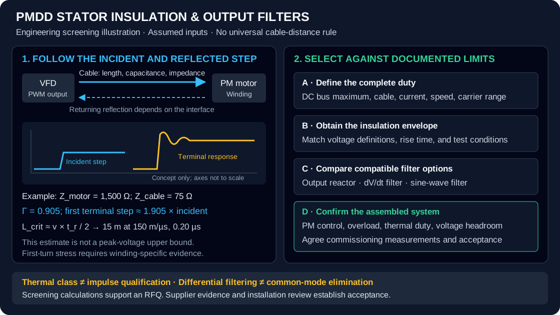
PMDD Stator Insulation & dV/dt Filter Sizing: Cable Reflection, PDIV Limits, and Output Filter Selection
Compare PMDD stator insulation and dV/dt filter sizing: cable reflection, PDIV evidence, and drive limits. Prepare an RFQ for a supplier compatibility review.
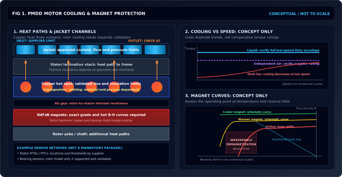
PMDD Motor Thermal Management & Cooling Sizing: Liquid Water Jacket, Forced-Air Convection, and NdFeB Magnet Thermal Limits
Size PMDD motor cooling with a worked flow example. Compare water jackets and forced air, check NdFeB thermal limits, and prepare your cooling RFQ for review.
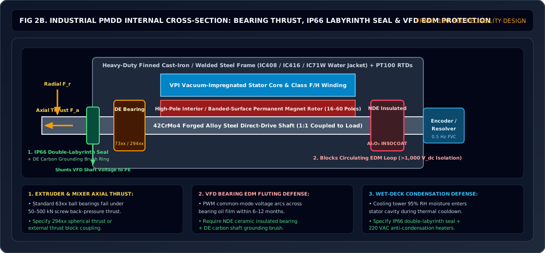
PMDD Bearing Sizing & EDM Protection: Thrust Loads, L10h Life, and VFD Shaft Currents
Size PMDD motor bearings for thrust and L10h life, compare VFD shaft-current protection, and prepare an RFQ with load, lubrication, and commissioning requirements.